Introduction
PVC/CPVC Molding Guide
PVC and CPVC Materials, Scientific Processing, Troubleshooting, Drying, Purging, and Other Practical Information — authored by Daniel Stephens
Plastics is a sophisticated and diverse discipline. To excel, you need a good grasp of a wide range of concepts and data. The purpose of this guide is to provide PVC/CPVC processors with information that can help them to process, document, and troubleshoot more effectively.
While Routsis Training hopes you find this information useful, it should not be considered a substitute for continuous education. Techniques and technologies are advancing rapidly throughout the industry, which is why top-performing professionals turn to companies such as Routsis Training to keep enhancing their knowledge and skills.
We invite you to further explore the topics covered in this guide through the comprehensive array of online training programs we provide at www.traininteractive.com.
Disclaimer
This reference guide contains general recommendations intended solely for informational use within the PVC & CPVC molding industry. It is not intended to serve as engineering advice.
The information contained herein is based on published information, knowledge, research, and experience which are presumed to be accurate and complete to the best of our ability.
All information is based on averaged data of commonly available grades of plastics and current industry practices at the time of this printing. Therefore, it is the user’s responsibility to review and confirm all design, calculations, and processing decisions.
You should always design and process using the recommendations that are provided by your raw material supplier, resin distributer, machine and equipment supplier(s).
Each material, machine, and process have their own set of influencing factors and, therefore, may or may not comply with the information provided in this guide. Routsis Training, LLC will not accept responsibility or liability for use of the information contained within this guide.
Contact Us
Routsis Training, LLC
379 Amherst Street PMB 233
Nashua, NH 03063 (USA)
phone:(978) 957-0700
website:www.traininteractive.com
store:store.traininteractive.com
email: info@traininteractive.com
PVC & CPVC Polymers
Definition of PVC
Polymers are large molecular chains made up of many smaller molecules. The word polymer can be broken up into two parts:
- Poly means “Many”
- Mer means ”Unit”
- Polymer means “Many Units”
A polymer consists of many smaller molecules called monomers. These monomers are combined into longer polymer chains. The process used to combine these molecules is called polymerization. In most cases, the longer the polymer chains, the tougher and stronger the polymer.
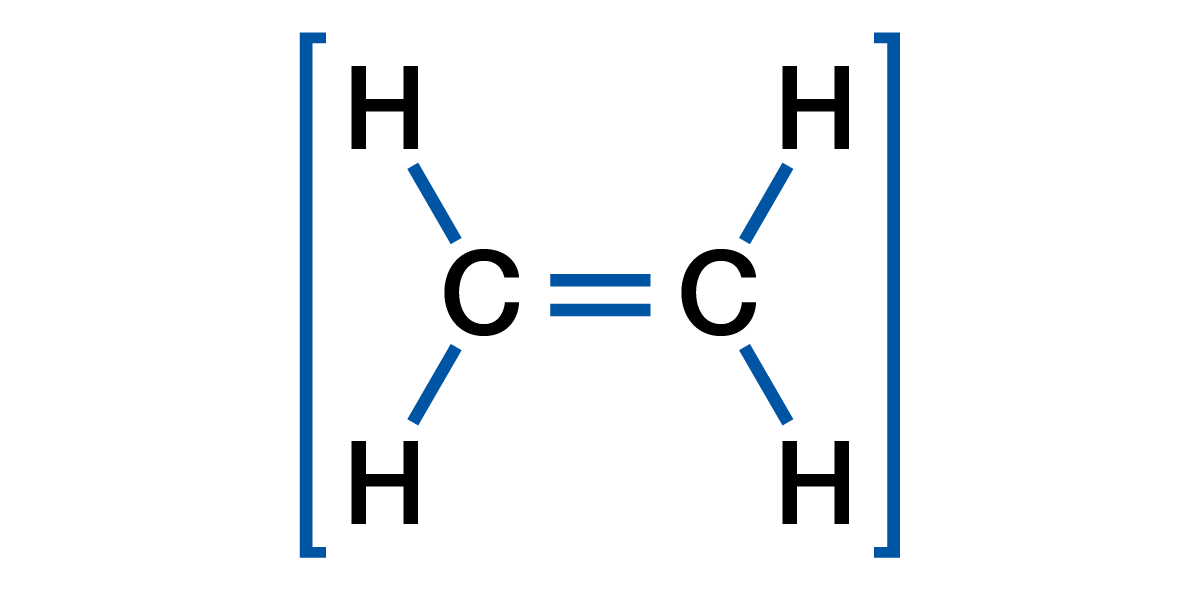
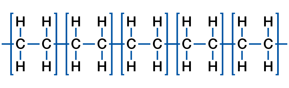
Polyethylene, for example, is one of the most commonly used polymers in the world. This polymer starts with an ethylene monomer of 2 carbons and 4 hydrogen atoms: When polymerized, Polyethylene is comprised of hundreds, thousands, or millions of repeating Ethylene units.
Smaller polyethylene chains (consisting of only hundreds of repeating units each) are often used for low strength applications, such as candle wax. Longer polymer chains make stronger polyethylene, which can be used for injection molding, extrusion, and blow molding processes.
Polyethylene, like all polymers, gets much of its strength from the entanglement of all these relatively long polymer chains. This strength is the highest when the polymer is cooled and the atoms are in a ‘low energy’ state where they are difficult to move around and untangle.
Ethylene Monomer
Polyethylene Polymer
PVC Polymer
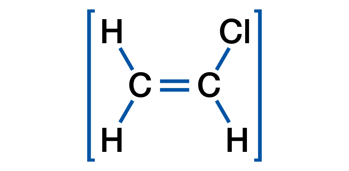
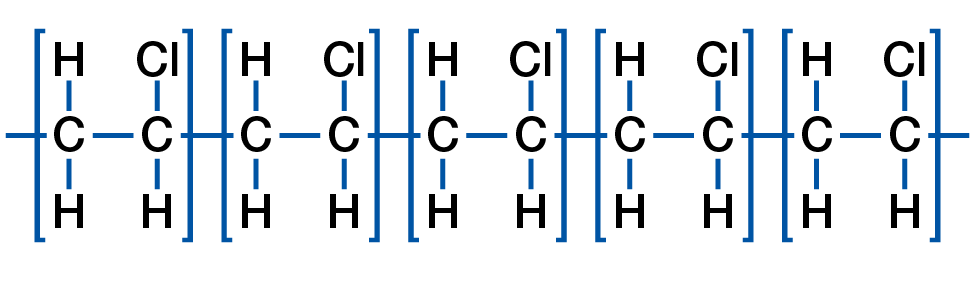
The Polyvinyl Chloride, or PVC, polymer starts with a monomer known as Vinyl Chloride. Vinyl Chloride is comprised of 2 Carbon, 3 Hydrogen, and 1 Chlorine atom.
When polymerized, the Vinyl Chloride monomer becomes the Polyvinyl Chloride polymer which is commonly known as PVC.
Vinyl Chloride Monomer
Polyvinyl Chloride Polymer
PVC gets very rigid when it cools, thus when these stiff PVC chains entangle, they gain a lot of strength. This chain entanglement contributes to much of PVC’s overall strength. The atoms on one polymer chain are also attracted to atoms on adjacent chains resulting in significant intermolecular attraction. The combination of rigid chains and intermolecular attraction cause the PVC polymer to be very hard and rigid. This rigidity makes PVC very difficult to process as the polymer chains will break if subjected to too much work and shear when melting or processing. Viscosity is a material’s resistance to flow, the higher the resistance to flow, the higher the viscosity. The rigidity of PVC causes the polymer to have a very high viscosity as compared to many other polymers.
The chlorine present on every unit of the PVC polymer chain causes material be less heat stable than most polymers during processing. When melt processing PVC, it is always important to avoid processing the material with too much heat or shear. When PVC degrades, one byproduct is chlorine gas, which is very dangerous and corrosive when not properly ventilated. The byproduct of degraded PVC will cause any PVC it comes in contact with to start degrading immediately. If excessive PVC degradation occurs, the result could be a cloud of chlorine gas or an explosion, both of which are very dangerous and potentially deadly. These gasses also contribute to the corrosion of metal surfaces such as the screw, barrel, die, and any exposed metal around the processing equipment.
When processed, PVC gives off a highly corrosive chlorine gas. This chlorine gas will accelerate rust, corrosion or oxidation on any surface it encounters including stainless steel. It is imperative that all exposed machinery and die surfaces are routinely cleaned, lubricated, or protected to prevent premature corrosion. There are also chlorine neutralizing sprays which can be used on the mold or die surfaces after processing PVC to reduce post-processing corrosion.
Chlorine and CPVC
PVC has good fire resistance, but the addition of chlorine to the PVC polymer chain will further increase the heat and fire resistance of the end product. Additional chlorine can be added through chlorination making a more rigid material known as Chlorinated Poly-Vinyl Chloride or CPVC. The extra chlorine increases chain rigidity and intermolecular attraction making the polymer very strong, rigid, and more difficult to process.
CPVC is challenging to process because it is much more rigid than PVC — with a much higher viscosity. CPVC is so rigid that it can be difficult to process without causing material degradation. For most of the remainder of this guide, PVC and CPVC will be used together as the concerns when processing the two materials are similar even though CPVC is more difficult to process.
Crosslinking of PVC or CPVC
The Vinyl Chloride monomer is turned into the PVC and CPVC polymer during polymerization. Most grades of PVC/CPVC will polymerize into long chain thermoplastic polymers.
Under the right conditions such as when degrading or when exposed to radiation, PVC and CPVC will cross-link. Crosslinked polymers are called thermoset polymers. These thermoset PVC/CPVC polymers are less common because they cannot be reground and re-processed. The remainder of this guide only focuses on the processing of Thermoplastic PVC/CPVC polymers and does not cover thermosets.
PVC & CPVC Components and Additives
Any additive, plasticizer, colorant, and heat stabilizer must be properly combined into a homogenous mix with the PVC or CPVC during processing or the material will not reach peak performance.
Fillers & Additives
Many different fillers and additives such as Talc, Calcium Carbonate, Sodium Sulfate, Glass Fibers, and colorants can be added for many reasons. Additives and fillers are introduced early in the polymer blending process. These could be added to reduce the cost of the material, increase the strength of the material, change the color, adjust the gloss, or even increase the density of the material.
Plasticizers
Due to the rigidity of PVC and CPVC, plasticizers are added during blending to help the polymer flow when processed. Large amounts of plasticizers are added when flexible PVC polymers are being blended. Plasticizers are usually comprised of smaller molecules which reduce the intermolecular entanglement or molecular attraction.
Rigid PVC and CPVC have a high viscosity because they use a minimal percentage of plasticizers to help flow, yet allow the final product to retain its stiffness. Rigid PVC and CPVC are commonly used for high strength applications such as plumbing pipes, pipe fittings, house siding, window frames, and control panels on ‘white goods’ such washing machines and dish washers.
Flexible PVC uses a much higher percentage of plasticizer to reduce the stiffness of the intended products. A further benefit of using a plasticizer is that it reduces the viscosity of the PVC. Common uses for flexible PVC are tubing, synthetic leather, shower curtains, films, and gaskets.
Heat Stabilizers
PVC and CPVC degrade very easily. Heat stabilizers are added during polymer blending to help reduce degradation and improve thermal stability when processing. The most common heat stabilizers are metal-based and often include multiple elements such as tin, barium, and calcium. These additives can withstand heat much better than PVC or CPVC alone, which improves thermal stability during processing.
PVC & CPVC Regrind
Thermoplastic polymers can be reground and re-processed, but PVC and CPVC can only be reprocessed until they degrade. When PVC or CPVC degrades, the degraded material will cause any PVC or CPVC molecules it encounters to degrade quickly due to a rapid chemical reaction. For this reason, you cannot put degraded PVC or CPVC back into the process or it will rapidly create more degraded PVC in the barrel and in your final product.
Since PVC and CPVC degrade easily, you must always be careful when processing regrind. Good quality PVC and CPVC regrind may have value as can be reprocessed. Good quality regrind refers to reground material which has no contamination or degradation.
Bad quality PVC or CPVC regrind has a negative value and will not only create more scrap in your process, but will also lead to more degraded PVC or CPVC. It is more cost effective to discard bad PVC or CPVC as processing degraded regrind material will lead to increased scrap and production losses. If your PVC or CPVC has degraded regrind in the mix, then it will create more degraded PVC in your final product. Degraded regrind or contamination will create a lower quality part which will likely have reduced properties such as poor strength, impact resistance, chemical resistance, and appearance. Processing degraded regrind will increase the chances that faulty product will reach your customers.
Performance vs. Non-Performance PVC & CPVC
Processing Performance PVC or CPVC
Performance PVC and performance CPVC refers to plastic used for functional applications such as pipes, fittings, siding, films, hoses, tubing, bottles, and window profiles. These products must meet specific performance requirements such as tensile, flexural, compressive, impact strength, and/or resistance to chemicals, UV, or radiation. The PVC or CPVC reaches peak performance when all the additives, plasticizers, heat stabilizers, etc. are thoroughly mixed which is a condition known as gelation or fusion.
Without proper gelation or fusion, the performance products may fail during use. It is common for performance products to meet all visual and dimensional requirements but fail when put through performance testing. This is often the result of inadequate gelation in the final product. Gelation and fusion will be covered in later sections of this guide, but general discussions related to Performance PVC/CPVC is covered below.
Performance polymers should be close to peak gelation or fusion at the end of the process to achieve the highest possible performance. When polymers reach peak gelation or fusion, the PVC or CPVC cannot accept much more time, temperature, or shear before the polymer begins to start degrading. For this reason, it is very difficult to process regrind made from performance PVCs. Regrind performance PVC or CPVC degrades easier than the virgin material in the pellet or powder forms because it has an additional time, temperature, and shear history. When regrind is incorporated in performance PVC and performance CPVC applications, the percentage used is often below 10% to prevent potential degraded material from causing significant performance losses. Waste material which does not show any signs of degradation such as burning, streaks, dieseling, or die lines is considered as usable regrind.
Documenting Performance PVC or CPVC
Essentially, the correct balance of time, temperature, and shear will help the PVC or CPVC fully mix and approach peak gelation or fusion. When the process makes acceptable product which meets all the visual and performance requirements, is it critical to fully document the process. This process documentation should include all the factors which go into making a good product. Specifics will be covered in later sections of this guide, but general documentation guidelines are covered below.
Machine, auxiliary, and downstream information should be recorded with any critical process information. Detailed process output data should be recorded as well as any information which helps identify what made good product during the specific production run. This includes the material lot, blending facility and equipment, pelletizing facility and line, percentage regrind, and any rheological information such as melt flow index, dryer residence time, barrel residence time, material temperature, coolant temperature, and any results from post-production testing including dimensional and gelation-related data.
Detailed process documentation should identify the factors which specifically relate to gelation or fusion such as all time, temperature, and shear factors. This way, the processor has information to help make process adjustments to compensate for time, temperature, and shear factors differences between one production run and another.
Proactive Process Adjustments
For performance PVC or CPVC applications, good process documentation allows the processor to make predictive adjustments based on an expected change in the time, temperature, and/or shear in an upcoming run. For example, if an upcoming production run is going to contain regrind, the barrel temperatures can be reduced to help mitigate the additional heat the regrind adds to the process. If a production run is scheduled to be run in a machine with a smaller barrel, the barrel temperatures or pressures might need to be increased to put more temperature or shear into the material – this can help compensate for the shorter time the PVC or CPVC will spend in the smaller barrel.
When using different equipment or material from run to run, a modified process may be necessary to get the same product performance. As a processor, you can control aspects of time, temperature, and shear on the PVC or CPVC, but many times it is the role of the processor to compensate for changes they cannot control such as a different machine or lot of material. The more a processor can predict these changes, the less scrap will be produced and the higher the production efficiency your process will have.
A proactive approach is important for performance PVC and CPVC applications. This is because most performance testing requires a specified time to pass such as 12 or 24 hours before the product can be properly tested. If a processor can gain some skill and experience in making effective proactive process adjustments, then it is often possible to run production while the product waits to be tested because there is a high-level of confidence that the product being produced will meet all quality parameters including performance testing.
Reactive Process Adjustments
The first use of this data is to make process adjustments on setting up, followed by adjustments after the product is found to be defective. If the PVC or CPVC shows degradation, then there needs to be a reduction in time, temperature, and/or shear such as a reduction in screw speed, barrel temperature, or a change to a machine with a smaller barrel. Conversely, if there is not enough gelation, then the time, temperature and/or shear applied to the material will need to be increased to get more gelation.
When using the same or similar processing equipment, the same process should be used to maintain the same balance of time, temperature, and shear. The part is likely to perform the same in testing, but good documentation will help you determine and compensate for differences during startup.
Keep in mind that many flexible PVC or CPVC applications can be considered performance PVC or performance CPVC applications if they must meet specific performance requirements such as chemical resistance or chemical characterization testing which require the PVC to be at near peak gelation or fusion to pass.
Non-Performance PVC Products
“Non-Performance” refers to non-functional applications such as decorative parts like panels, trim, and appliance panels. These products tend to have specific visual and fit requirements, but the PVC or CPVC does not have to perform at or near its peak strength or resistance capabilities.
These parts should always be processed with the minimal time, temperature, and shear necessary to make good product. This strategy provides the processor with a larger process window with the least likelihood of degrading the polymer. If the PVC or CPVC is processed at conditions significantly lower than necessary to achieve peak gelation, the defective products and waste can be reground and reprocessed with a lower risk of degradation.
As with Performance PVC and Performance CPVC applications, it is important to document all factors that make acceptable product, including all process outputs, material data, and time, temperature, and shear information. The positive aspect to non-performance PVC and non-performance CPVC is that you can usually match up the process outputs on similar processing equipment and the process should make good product. The detailed process documentation will help you identify and make efficient reactive adjustments when a significant change occurs in the time, temperature, and shear relationship such as degradation.
When using significantly different material grades and batches, or changing machinery from run to run, a proactive process adjustment should be considered before the process is started. This is recommended for non-performance PVC/CPVC applications to increase the efficiency of a production run. However, it is not typically as critical as it tends to be with performance PVC/CPVC products.
Time/Temperature/Shear Relationship for PVC & CPVC
Performance vs. Non-Performance
Performance PVC and performance CPVC refers to polymers which must meet stringent strength or resistance properties. For the purpose of this guide, we will occasionally differentiate these polymers from non-performance PVC or non-performance CPVC polymers where the application may have specific appearance or dimensional requirements but does not have stringent performance requirements.
Gelation (Fusion) Concerns
Once the polymer, additives, plasticizers, heat stabilizers, and other components in PVC or CPVC are fully mixed, the polymer is at peak strength. This is known as gelation (or fusion) because all of the components have become combined or fused into what is known as a gel. Full gelation refers to the point where the polymer matrix has fully formed, and it has achieved its optimal strength.
It is important to note that performance PVC and performance CPVC plastics are provided to the processor in a blended form, but all the components are not fully mixed when in pellet or powder form. This is because the process to properly combine all these elements puts excess heat and shear into the polymer. If this is all done before final processing, then the polymer will start to degrade once it is re-melted to processing temperatures. It is the job of the processor to complete the combining of the Rigid PVC or CPVC with the desired additives in the barrel. When done properly, the plastic in the final product has adequate gelation to achieve the desired properties.
Rigid PVC or CPVC products which have not reached full gelation will have reduced physical properties such as low impact, flexural, tensile, or compressive strength. These polymers which have low-strength will also have reduced resistance to attack from chemicals, UV rays, and electricity. Low gelation can cause product failures in the field such as bursting pipes, breaking fittings, cracked siding, leaking containers, or even food contamination.
The biggest problem the performance PVC/CPVC processor faces is when the material has not reached high gelation. In this instance, the plastic product may look good and meet the dimensional requirements and preliminary quality checks, but fail when the final product is tested for performance such as a pressure, strength, crush, flexural, impact, or chemical testing.
For performance PVC or CPVC to reach high gelation, a proper combination of time, temperature, and shear must be applied to the polymer. Gelation will not occur if there is too little time, temperature, or shear involved in processing. Unfortunately, when too much time, temperature, or shear is applied to the PVC or CPVC, it will begin to degrade. Good PVC and CPVC processing is based on understanding the proper balancing of time, temperature, and shear for your specific application.
In the Process Documentation portion of this guide, we’ll review how to document time, temperature, and shear on your process documentation.
Time
With respect to time, temperature, and shear for performance PVC or CPVC, time refers to the time the PVC or CPVC is exposed to heat and/or shear. To effectively combine all the polymer components and additives, both heat and shear must be applied over a period of time. Time examples include:
- Barrel Residence Time
How long the polymer remains in the barrel exposed to heat - Cycle Time
The time required to produce a fixed amount of product - Dryer Residence Time
How long the polymer remains in the dryer exposed to heat - Blending Time
How long the polymer is exposed to heat and shear during component blending
If any PVC or CPVC is exposed to heat or shear for an excessive amount of time, the polymer will begin to degrade. If performance PVC or CPVC is not exposed to heat or shear for enough time, insufficient gelation will occur, and the resulting product will not meet the end use requirements.
This time factor is very important to consider during production stoppages, slowdowns, shutdowns, startups, and changeovers as the polymer will begin to degrade. This is why it is very important to replace all the PVC with heat stable polymers immediately whenever the processing equipment is to be down or idle for any extended period of time.
Temperature
Temperature refers to the heat history applied to the PVC or CPVC. To effectively combine all the components, heat is a necessary factor. Without applying heat, the PVC and CPVC polymer chains would be too rigid to properly mix. Temperature examples include:
- Blender Temperature
- Barrel Zone Temperatures
- Die or Hot Runner Temperatures
- Dryer Temperatures
- Coolant Temperatures
Temperature control is critical with PVC or CPVC. A temperature spike occurring anywhere during mixing, pelletization, drying, or processing can start the degradation process. To reduce heat generation, PVC or CPVC molding machines and extruders should use barrel heaters equipped with cooling fans. These fans circulate air around each barrel zone to prevent the material from overheating. In many instances, cored extruder screws cooled by air or oil mail may be used to help prevent overheating of the polymer during processing.
Shear
Shear refers to the work or mechanical energy applied to the PVC or CPVC. To effectively combine all the components, shear is a necessary factor as the polymer must be thoroughly mixed. Examples of when PVC or CPVC is sheared include:
- Material mixing and blending
- Pelletization
- Screw rotation and screw geometry, features and characteristics
- Back pressure or die head pressure
- Material flow through the die or mold
- Restrictions or blockages in the die or mold
With PVC or CPVC, shear creates significant heat. Always be very careful whenever adding shear to a PVC or CPVC process. Adding both energy and heat can bring the material to the point of degradation very quickly.
Gelation (Fusion)
The point where PVC or CPVC approaches peak mixing of components is called gelation (or fusion). When gelation occurs, the PVC or CPVC polymer has the highest strength, impact resistance, chemical resistance, heat resistance, fire resistance, and UV resistance. Gelation is critical for high performance PVC or CPVC products such as pipes, fittings, containers, siding, window casings, and medical tubing.
Incomplete or non-gelation: Many parts look good after processing but have not reached gelation resulting in lower mechanical and resistance properties. In most cases where performance is critical, insufficient gelation will often result in parts failing during use.
Non-gelation is generally acceptable for applications such as appliance panels, decorative components, and other low-risk applications where fit and appearance is more important than performance.
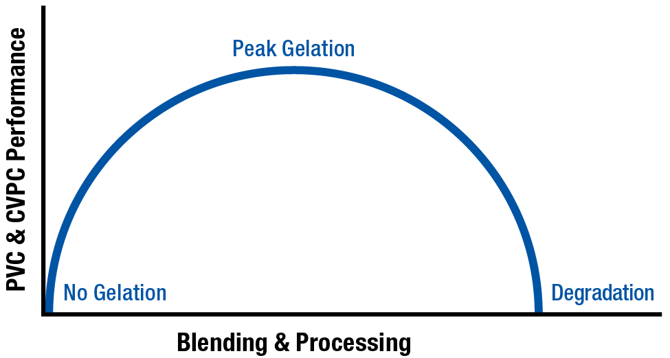
The figure below shows the starting state of polymer with the lowest strength at ‘No Gelation’. Once the polymer starts receiving a time, temperature, and shear history the strength of the polymer increases with corresponding increase in gelation. Once too much time, temperature, or shear is applied, the PVC or CPVC will start to degrade resulting in a loss in polymer properties the more it degrades.
PVC/CPVC Gelation Arc
PVC Degradation
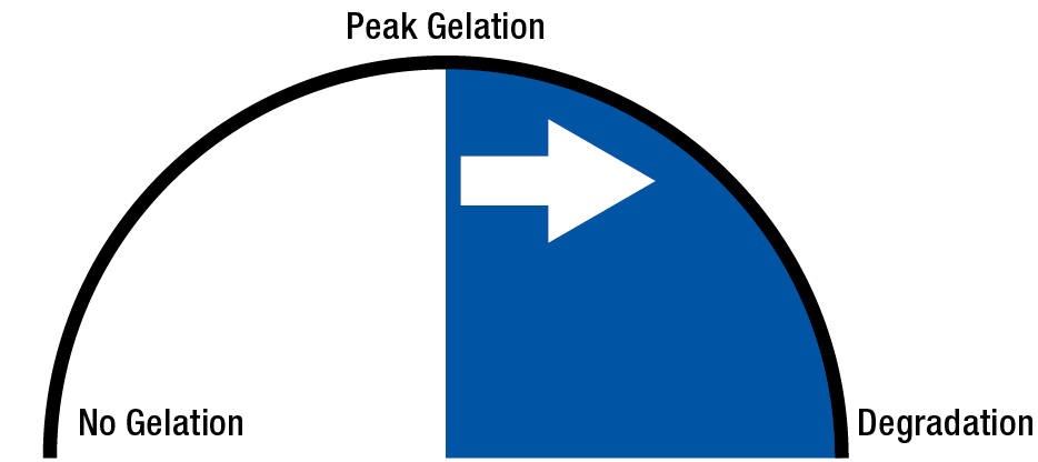
Once a high level of gelation or fusion is achieved, additional time, temperature, or shear will begin the degradation process. Once PVC or CPVC begins to degrade, it undergoes a chain reaction which accelerates more degradation of adjacent PVC chains.
This degradation chain reaction is a primary reason why it’s critical that all PVC or CPVC processing equipment is streamlined: without any gaps or hang-up points where the polymer flow can stop. If the PVC or CPVC stagnates at any point, the stagnated polymer will degrade — in turn, causing all polymer that touches it to degrade.
This degradation is often seen in extrusion in situations where degraded PVC/CPVC is present inside or on the edge the extrusion die. This will cause a continuous brown stripe in the extrudate until the degraded material is removed from the die. Another example of this is degraded material in the nozzle of an injection molding machine. This degraded PVC or CPVC will cause brown streaks on the gate area of the molded parts on every cycle until the process is stopped and the nozzle is properly cleared of degraded material.
Excessive PVC degradation is very dangerous. As mentioned before, polymer chains degrade in a rapid, continuous reaction. Toxic chlorine gas can be produced rapidly and the polymer chains can crosslink and seize the screw inside the barrel. PVC or CPVC cannot be left in the barrel for any extended period of time. Rather, it must be replaced with a heat stable material, such as a Polyolefin (PE or PP) or Purging Compound.
Testing of Gelation or Fusion of PVC & CPVC
The only way to know the amount of gelation or fusion in your PVC or CPVC after being processed is to conduct a test on the material using one of the following tests. All the tests in this section apply to testing of the final product. In all cases, the final product testing is destructive, thus you will not be able to sell the product after gelation or fusion is tested.
Chemical Immersion Test
In this test, the PVC is immersed in a chemical for a pre-determined amount of time to visually evaluate the amount of damage the chemical does to the polymer. To conduct this test, the PVC or CPVC sample is cut at an angle to help expose a large amount of internal surface area to the chemical. The internal surface of the PVC must be exposed for this test to provide accurate results because the outer surfaces tend to develop a skin which may resist chemical attack.
For example, ASTM D2152-17 entitled ‘Standard Test Method for Adequacy of Fusion of Extruded Poly (Vinyl Chloride) (PVC) Pipe and Molded Fittings by Acetone Immersion’ uses product which is cut and submersed in acetone for a specified period of time.
If the processed PVC or CPVC have a high amount of gelation or fusion, the PVC or CPVC will show no signs of attack at the end of this chemical immersion test. This means the product has passed the test and is likely to have good strength and resistance properties due to a high degree of gelation or fusion.
If the PVC or CPVC sample shows discoloration, pitting, streaking, or any noticeable change in appearance, the polymer components have not been properly mixed, or some degradation has begun to occur. In either case, the polymer matrix does not have enough gelation or fusion.
The chemical immersion test is a common general test for gelation or fusion because poorly gelated PVC or CPVC will be easily attacked. This is because all the components have not been blended into a cohesive polymer matrix.
The challenge with this test is that the person evaluating the results must have the necessary experience to evaluate minor attacks on the PVC or CPVC. The results of this test are generally considered pass or fail, but an experienced technician can provide a subjective evaluation on the degree of attack and type of damage which has been done to the sample by the chemical.
Aside from Pass or Fail, the results of this test are not quantitative, but observational data can be helpful to the technician – for example, pitting in the tested sample might indicate poor mixing while streaking in the sample may indicate degraded polymer.
The general methodology of the chemical immersion test is straightforward:
- The test sample is prepared by cutting it with an angle to expose the internal polymer
- The area of the sample being tested is submerged into the chemical for a period of time
- The sample is removed and chemical is washed off to make the sample safe to handle
- The exposed polymer is visually inspected to determine whether the polymer passed or failed
Advantages & Disadvantages
There are several advantages and disadvantages associated with using the Chemical Immersion Test to evaluate the gelation or fusion of PVC and CPVC materials.
Advantages:
- Many chemicals are available for use in this test
- Testing is easy to perform
- Cost is low
Disadvantages:
- The test takes a significant amount of time to complete
- The chemicals used can be very dangerous
- Proper PPE and ventilation are required
- Evaluation requires training and experience
- Evaluation of results are very subjective
- Test results are not quantitative
Impact Strength Test
In this test, the PVC or CPVC is subjected to a high-speed impact of a specific weight moving at a specific speed which is measured as energy. In some tests, the sample breaks and the loss of energy is measured. In other tests, the sample is tested at a specific energy level to determine if it will break or not. This is a pass/fail test. With respect to PVC or CPVC, the better the part performs in testing, the more gelation is likely present in the product.
Pendulum Impact Strength Test
The most common form of impact strength test is the pendulum test. In this test, a weighted pendulum is swung through the test sample to break it. The pendulum starts on one side of the testing apparatus from a fixed point and the highest position of the pendulum’s upswing is measured. This measurement corresponds to the amount of energy lost as the pendulum passed through the sample. The less the pendulum swings afterward, the more energy has been lost during the breaking of the sample. In theory, properly gelated product will have a higher energy loss when being tested than low gelation product does.
Different tests may use different weights and methods for holding the sample. For example, ASTM D2560-10 titled ‘Standard Test Methods for Determining the Izod Pendulum Impact Resistance of Plastics’ uses a notched sample which is struck while clamped in a vertical orientation.
The general methodology of different pendulum impact testers is common:
- The test sample is prepared by cutting it to size and often is notched to reduce the effects of the outer polymer skin from skewing the test results
- The sample is secured in the testing apparatus
- The swinging weight is lifted and released from a fixed point
- The energy loss is measured
Falling Weight Impact Strength Test
The falling weight impact test is a simple way to test the impact resistance of a product. These tests use a weight with a piercing element which is dropped from a specific height. The test is designed to determine whether the product resists puncture in a pass or fail evaluation. The energy used in the test is created by the dropping of the weight in the test. In most cases, the product has a specific weight and height impact that it is designed to resist. When the test is designed properly, a well-produced and gelated PVC or CPVC product will pass this test by resisting puncture, while poorly manufactured product will fail the test. Different tests use different weights and points for puncturing the sample. In many applications, the final product is fixtured under the falling weight. This tests how a product will perform when impacted by something realistic such as a hammer.
Different tests may use different weights and methods for holding the sample. For example, ASTM D5420-21 titled ‘Standard Test Method for Impact Resistance of Flat, Rigid Plastic Specimen by Means of a Striker Impacted by a Falling Weight (Gardner Impact)’ offers different product geometries, weights, and heights for standardized testing.
The general methodology of falling weight impact testers is common:
- The test sample is prepared by cutting it to size (where applicable)
- The cut sample or finished device is secured in the testing apparatus
- The falling weight is lifted and released from a fixed height
- The sample either passes or fails the test based on whether the product is punctured
Advantages & Disadvantages
There are several advantages and disadvantages associated with using Impact Strength testing to evaluate the gelation or fusion of PVC and CPVC materials.
Advantages:
- Many testing systems are available
- The tests are relatively easy to perform
- Results are easy to evaluate
- Pendulum impact testing is quantitative
- Falling weight impact testing is easy to perform final product
Disadvantages:
- Apparatus used can be dangerous
- Poor results are not always caused by poor gelation or fusion
- Falling weight impact testing is not quantitative
- Extensive testing of good and bad product required to determine pass or fail criteria
Mechanical Strength Test
The purpose for using mechanical strength testing for performance PVC and CPVC is that high-performing product has adequate strength as a result of good processing and adequate gelation or fusion. With any mechanical strength testing, the overall strength of the product being tested can be heavily influenced by the process used to manufacture it. This means that a failure in strength testing could be indicative of a bad process and not necessarily inadequate gelation or fusion.
Since a good product is expected to pass strength testing requirements, this testing method is a good measure of overall product quality, which includes adequate gelation of the PVC or CPVC in the final product.
There are many mechanical testing methods used for testing, but the most common are:
- Tensile Strength (ASTM D638)
Tests resistance to being pulled apart - Compressive Strength (ASTM D695)
Tests resistance to being compressed or crushed - Flexural Strength (ASTM D790)
Tests resistance to being bent or flexed - Pressure Strength (ASTM D1785)
Tests resistance to bursting or leaking under pressure
When tested, the sample is subjected to either a steady strain and the stress and/or failure is measured, or the sample is tested at an increasing stress and the strain and/or failure is measured. In many cases, the strength of the final product can be tested with a properly designed testing apparatus – for example, Pipe fittings are often filled with water and tested with increasing pressure until the product fails by leaking or bursting.
The general methodology of strength testing is common such as:
- The test sample is prepared for the testing apparatus
- The sample is secured in the testing apparatus
- The sample is subjected to either an increasing stress or an increasing strain
- The stress or strain at failure is measured.
Advantages & Disadvantages
There are several advantages and disadvantages associated with using Mechanical Strength testing to evaluate the gelation or fusion of PVC and CPVC materials.
Advantages:
- Many testing systems are available
- The tests are relatively easy to perform
- Results are easy to evaluate
- Most strength testing is quantitative
- Strength testing can often be used on the final product
Disadvantages:
- Apparatus used can be very dangerous
- Poor results are not always caused by poor gelation or fusion
- Extensive testing of good and bad product required to determine pass or fail criteria
Thermogravimetric Analysis (TGA) Test for Gelation or Fusion
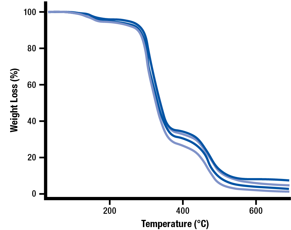
A Gravimetric Analysis test uses a polymer sample placed on a very accurate scale. The sample is subjected to a steadily increasing temperature and the weight loss of the sample is measured. The result of the test is a curve showing the percentage weight loss in the sample on the vertical Y axis and the temperature of the sample on the horizontal X axis. This is known as a gravimetric curve.
Since the test involves heating and burning PVC or CPVC, proper PPE and ventilation is required to conduct this test.
The purpose in using Thermogravimetric Analysis testing for performance PVC and CPVC is that highly-gelated polymer matrix will require a higher temperature to burn off the polymer, resulting in a very specific thermogravimetric curve. This curve would be characteristically different than the thermogravimetric curve of an un-blended or degraded PVC or CPVC polymer.
The person evaluating the test results is responsible for analyzing the gravimetric curve by comparing it to a gravimetric curve of a sample known to have good gelation or fusion. Some systems can determine how much the sample curve differs from the standard, but many thermogravimetric comparisons must be done manually.
The general methodology of Gravimetric Analysis testing is as follows:
- A small test sample is cut from the center of the product
- The scale is zeroed and the sample is placed into the Thermogravimetric Analyzer to be weighed
- The sample is subjected to a heat source which steadily increases the temperature of the sample
- The weight is constantly measured by a computer which generates a gravimetric curve
Sample TGA Graph
Advantages & Disadvantages
There are several advantages and disadvantages associated with using Thermogravimetric Analysis (TGA) to test the gelation or fusion of PVC and CPVC.
Advantages:
- Many low-cost TGA systems are available
- The tests are relatively easy to perform
- The test is evaluating the polymer itself
Disadvantages:
- High-accuracy TGA systems are expensive
- Low-cost TGA systems have poor ventilation
- Evaluation requires training and experience
- Comparative testing of good and bad product is required to determine pass or fail curves
Differential Scanning Calorimetry (DSC) Test
The Differential Scanning Calorimetry (DSC) system heats the polymer sample at a specified rate while the heat flow from the sample is measured. The result of the test is a curve showing the heat flow of the sample on the vertical Y axis and the temperature of the sample on the horizontal X axis.
Since the test involves heating of PVC or CPVC, proper PPE and ventilation is required to conduct this test.
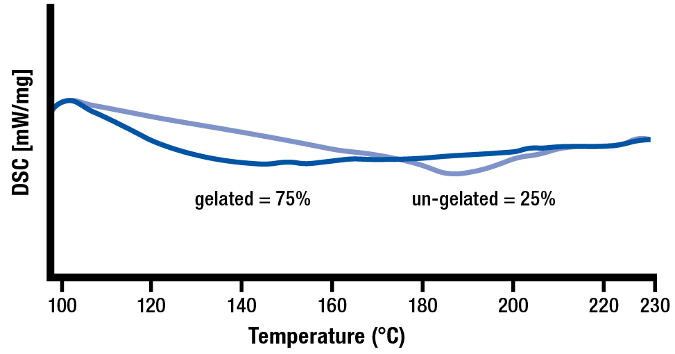
The purpose in using Differential Scanning Calorimetry (DSC) testing for performance PVC and CPVC is that a 100% gelated or fused polymer matrix will heat up as one component because they are fully combined. In contrast, any un-gelated heat stabilizers and fillers will heat up a different rate than the rest of the polymer components. Since it is rare to achieve 100% gelation, the results will have 2 dips in the curve. The area of these curves represent the amount of material which is gelated in the first portion and the amount of un-gelated or unfused material in the second portion.
The DSC software can determine the amount of PVC or CPVC that is in the gelated and un-gelated portion of the DSC curve.
The general methodology of Differential Scanning Calorimetry testing is common:
- A small test sample is cut from the product
- A sample is sealed into a container and an empty comparison container is also sealed
- The samples are placed into the DSC machine and the machine cycle is started
- The sample is subjected to a heat source which heats the sample as well as the comparison containers
- The heat flow for both containers is constantly measured by a computer which generates a heat flux curve and calculated the percentage of gelation or fusion
Example of DSC Curve for 75% Gelation of Fusion
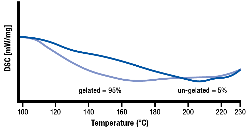
Example of DSC Curve for 95% Gelation of Fusion
Advantages & Disadvantages
There are several advantages and disadvantages associated with using Differential Scanning Calorimetry (DSC) to evaluate the gelation or fusion of PVC and CPVC.
Advantages:
- The test is evaluating the polymer itself
- Percentage gelation is analyzed and provided by the DSC system
Disadvantages:
- DSC systems are expensive
- Sample preparation requires training and experience
PVC & CPVC Powder, Pellets, and Regrind
Powder
Many processors use PVC or CPVC powder, which is commonly compounded in-house using large blenders. This powder is mixed and blended at controlled shear rates and temperatures to help provide a consistent material source with the same amount of time, temperature, and shear history with each batch.
It is best to use the same blending equipment for each lot to prevent variation in the quality of your PVC/CPVC source material. Most material suppliers can provide you with information about the blending equipment used and the location of the facility. Many suppliers will be able to provide you with material from the same facility or line if you work with them.
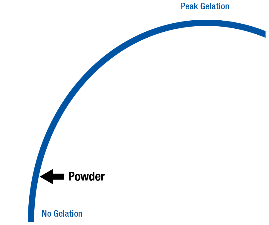
When powder is melted and processed, most of the gelation takes place in the barrel. The processor has significant control over degree of gelation when the PVC/CPVC is in powder form. Keep in mind, powders from different suppliers will have completely different time, temperature, and shear histories — requiring significantly different processes to obtain similar final part performance.
With powder, the processor controls a high percentage of the gelation (or fusion) during processing.
PVC or CPVC Powder on Gelation or Fusion Arc
Pellets
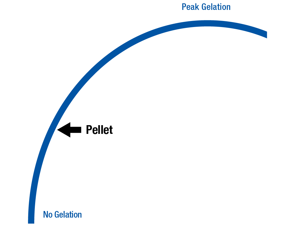
When PVC or CPVC powder is processed into pellets, the polymer is exposed to another time, temperature, and shear history. Pelletization takes place in an extruder — where the powder is melted, extruded, and cut into pellets. As a result, more progression towards gelation has occurred in the pellets when compared to its original powder form.
It is critical that your pellet supplier uses the same blending equipment and extrusion line to process your PVC/CPVC pellets. A change in equipment or processing conditions significantly changes the amount of gelation present in the pellets you receive. Essentially, PVC and CPVC lots received from different pelletizing lines will have different time, temperature, and shear histories — requiring different amounts of work during processing to reach peak gelation.
PVC/CPVC powders are very sensitive to time, temperature and shear when compounding into pellets. During pelletizing the blending and extrusion equipment are critical to these properties and should not be altered from lot to lot, as changes may affect material properties. All changes in time, temperature, or shear during the pelletization process must be communicated by the material supplier since these changes can alter the final process. When pellets incur more processing time/temperature/shear, they are likely to encounter increased degradation when processed.
With pellets, the processor typically controls half of the gelation process.
PVC or CPVC Pellets on Gelation or Fusion Arc
Regrind
There are many concerns when processing reground PVC and CPVC since the regrind material already has multiple histories of time, temperature, and shear. These concerns include:
- Powder Blending and Mixing
- Polymer Pelletizing
- Material Drying
- Melt Processing
- Grinding into Regrind
All of the above processes involve exposing the polymer to heat and shear. Sometimes this exposure takes place for hours as with material drying. Low RPM grinders are strongly recommended when regrinding PVC and CPVC, as they generate less heat during the grinding process.
Since the PVC/CPVC may have reached peak gelation, the reground material is much closer to degradation than it was in powder or pellet form. PVC or CPVC regrind is very difficult to process without causing degradation; therefore, lower percentages of regrind are always preferred. Frequent testing and inspection should also be used whenever processing with PVC/CPVC regrind to help identify any degradation that might be occurring.
Be cautious when mixing PVC Pellets with PVC Regrind since they both have different time, temperature, and shear histories. The resulting product may be inconsistent and should be closely monitored. For these reasons it is very important to closely monitor your incoming stream of PVC and CPVC regrind. Higher percentages or low-quality PVC/CPVC regrind will limit the amount of gelation possible with the final product.
Burnt or Degraded PVC or CPVC
You should never regrind and reprocess burnt or degraded PVC or CPVC. This material has negative value as it will cause rapid degradation of any PVC or CPVC it contacts. Any burnt or degraded PVC/CPVC material that enters the barrel will begin a chain reaction which can reduce the visual appearance, physical properties, and resistance properties of your final product. This means that a small percentage of degraded PVC/CPVC will prevent the material from reaching peak gelation render the final product useless. This is why the use of regrind must be strictly controlled and monitored in any performance PVC/CPVC applications where high percentages of gelation is required.
Too much burnt or degraded PVC or CPVC entering the barrel creates an extremely dangerous situation, which can result in the release of toxic chlorine gas — and an explosion of the barrel, endcap, or hopper. All of these situations have been known to cause serious injury and death at PVC/CPVC processing facilities.
For this reason, it is recommended to avoid putting any visually burnt or degraded polymer in the regrind stream. Sometimes this involves throwing away the entire piece, but it may involve cutting away the burnt or degraded section and retaining the rest of the piece.
Some companies invest in high-speed particle sorting equipment, such as those used in food applications to separate contaminants. As long as your part is not dark in color, these systems can visually sort out pieces of burnt and degraded regrind from the good regrind. These machines are not perfect, but can be great way to help maintain a better, more reliable quality of regrind material.
There are many ways to mitigate the creation of burnt PVC or CPVC, but there are no truly safe ways to reprocess degraded PVC or CPVC. Essentially, degraded or burnt PVC/CPVC should be considered waste and thrown away accordingly.
Burnt or Degraded PVC or CPVC on Gelation or Fusion Arc
Purging PVC/CPVC Materials
Definition
By definition, to purge is ‘to get rid of.’ In the case of extrusion, purging ensures that contaminants are removed to prepare for a new, contaminant-free application.
Contaminants include the following:
- Particles, dirt, and dust
- Paper
- Cardboard
- Colorants and additives
- Degraded material and carbon buildup
- Metal flakes from the screw, barrel, and check ring
- Rust from the screw, barrel and die
Safety Concerns
PVC can never be processed in the same extruder that has used Acetal. Likewise, an extruder that was used for Acetal cannot be used for PVC or CPVC. Any combination of Acetal and PVC/CPVC produces a deadly gas and may also cause an explosion.
There is no material or purging procedure that will allow you to safely process these two incompatible plastics in the same extruder. Properly review all recommended procedures and safety precautions before removing the screw. These operations are highly machine-specific — and injury or death can occur if handled improperly.
Personal Protective Equipment that is required during purging includes:
- Face Shield (or Purge Guard)
- Heat Resistant Gloves
- Long Cotton Sleeves
- Long Pants
- Closed-Toed Shoes
When purging, it is imperative to keep clear of the front zone of the extruder and to never reach around or under the die. Never attempt to clear the die or touch purge with your hands. A brass, plastic, or wood tool should always be used to handle purge. Purge can reach 400 °C (750 °F) and can remain dangerously hot for a long period of time.
Here are some additional guidelines to ensure the safety of yourself and your co-workers:
- Be responsible and aware of your surroundings
- Inform others around you of your tasks
- Never rush
- Follow procedures
- Avoid distractions
- Use the appropriate tools
- Ask for assistance if needed
- Always follow Lock-Out/Tag-Out protocol
PVC and CPVC are heat-sensitive materials that can begin degrading in only a few minutes. Some unstable materials (including PVC and CPVC) have the ability to create dangerous gases when they degrade. These gases can create pressures that may cause the barrel to explode if the material is left in the heated barrel for too long.
Corrosion & Oxidation Concerns
The chlorine in PVC & CPVC promotes corrosion on any surface it touches. The chlorine gas that is given off when processed promotes corrosion and oxidation of any metal surface it contacts.
Many processors tend to ‘empty’ the barrel when purging the processing equipment, which should always be avoided especially when processing PVC or CPVC. An ‘empty’ barrel will always have residual polymer left inside on the screw and barrel surfaces. This residual PVC or CPVC will degrade and give off chlorine gas which will corrode the screw and barrel surfaces. Since the barrel is heated and mostly filled with oxygen, rust-causing oxidation will be accelerated on all screw and barrel surfaces.
In all cases, whenever the machinery is to be stopped for a period of time, the barrel should be filled with a heat-stable material, such as a purging compound.
Heat-stable materials will minimize corrosion & oxidation during shutdowns and production stoppages. Hot runner molds should be filled with a heat-stable material to minimize corrosion from degrading PVC or CPVC.
Off-specification (off-spec) extrusion-grade Polyolefins and Polystyrenes are also commonly used for purging PVC & CPVC. Off-spec lots are those that do not meet quality requirements and thus cannot be sold to customers for production use. These lots can often be obtained through your material supplier at a discounted rate.
Large Shot Purging
Large Shot Size purging is defined as using a shot size over 50 percent of the maximum shot size. Large shot purging should not be used with PVC & CPVC, since it only cycles the check ring a few times. Due to the larger injection stroke, this method leaves particulates in the feed zone of the screw.
Small Shot Purging
Small Shot Size purging is defined as using a shot size of approximately 10-20% of the machine’s capacity. Small-shot purging involves making many small shots of purge and is preferred when processing PVC or CPVC because it cycles the check ring multiple times. This option will also clear out the feed zone of the screw when purging.
Dry Purging
Dry purging refers to purging the barrel ‘empty,’ leaving a significant amount of polymer baked onto the screw and barrel surfaces. This baking plastic gives off heated chlorine gas, which is corrosive to the screw and barrel surfaces. When the chlorine gas contacts the metal in the presence of heat & oxygen, the process of oxidation or rusting of the screw and barrel surfaces will be greatly accelerated. Dry purging your barrel will result in faster oxidation and corrosion of the screw and barrel surfaces.
Dry purging with PVC and CPVC will coat barrel and screw surfaces with baked & degraded material. Degraded PVC or CPVC creates a chain reaction that degrades the non-degraded PVC or CPVC it comes in contact with. The only way to stop this chain reaction is to purge all the degraded PVC and CPVC off the screw and barrel surfaces – this process uses a lot of purging compounds and consumes a lot of time. This situation can usually be avoided when using the wet-purging technique.
For these reasons, Dry Purging is not recommended for any polymer.
Wet Purging
Wet Purging refers to always keeping the barrel full of material. During production, the barrel should be full of PVC or CPVC. When a shut-down or process interruption occurs, the barrel should be filled with a more stable polymer, such as extrusion-grade polystyrene or polyolefin purging compound. When production resumes, the barrel contains little to no degraded PVC, which helps the technician get the process up and running quickly.
Keeping the barrel full of material also helps maintain positive conveyance of the material during purging, which reduces the stagnation and degradation of PVC and CPVC.
To conduct an effective wet purge, there should be an easy way to empty and clean the hopper, such as a sliding or swinging hopper. Such a hopper can be moved away from the feed throat to stop the transfer of material into the barrel while exposing the feedthroat. With the feedthroat exposed, the technician can quickly follow the PVC or CPVC with a more stable material to safely fill the barrel and avoid degradation. If the machine is to go back into production soon, the hopper can be slid or swung back into position for a quick purge and restart.
At each purging step, the technician should use a telescoping mirror to view the feedthroat and stop purging when the flights of the screw are exposed. The slide or swing hoppers should also have a method of safely emptying the hopper to recover the unused material into a bucket or container during every shut-down or long-term stoppage.
Melt Processing
The purpose of melt processing is to first melt the source polymer from a pellet, powder, flake, or regrind state. This polymer melt is combined and mixed with any needed additives, reinforcements, fillers, or colorants, inside the barrel. Lastly, the melted polymer is converted to a useful or sellable product such as a sheet, film, profile, tube, or plastic pellets.
PVC & CPVC plasticizers, fillers, additives, and heat stabilizers are not fully mixed before processing. During melt processing these components are combined into a polymer matrix often referred to as a gel. Full gelation (or fusion) refers to the point where the polymer matrix has fully formed or gelled and it has achieved its optimal strength. When high performance is required, the goal of processing is to get the PVC/CPVC to a near full gelation state when the final product is formed. More on this topic is covered in the chapter entitled ‘Time, Temperature, and Shear.’
Melting PVC & CPVC
When processing polymers, energy is added to the polymer in the form of heat and shear. Heat is typically provided by heater bands around the barrel. Shear is applied through the use of a screw inside of the barrel which rotates in a process which both works and heats the polymer. The material enters the barrel at the Feed Throat where the screw flights are the deepest as a powder, pellets, and/or regrind.
Screw & Barrel Assembly
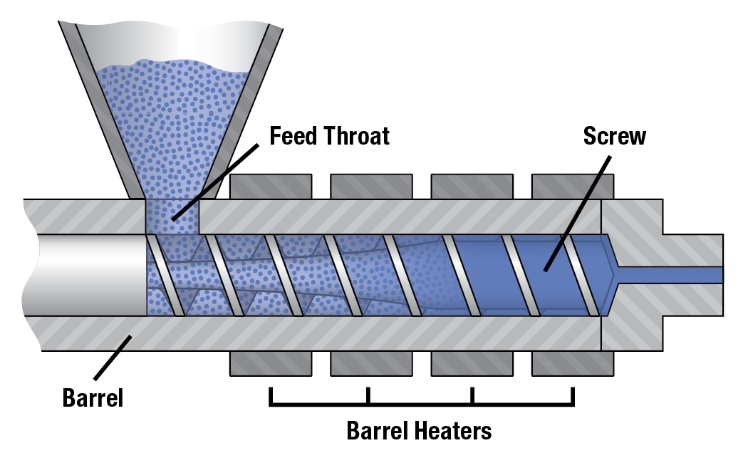
If too much heat or shear is used during processing, the polymer can begin to degrade. To help accurately control the temperature of the polymer, most barrels for extrusion are equipped with cooling fans around the heater bands to prevent the polymer from getting too hot.
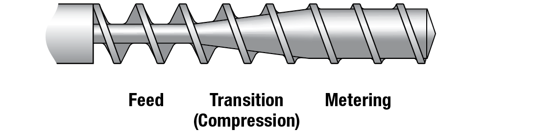
The Feed Zone of the screw has the deepest flights for the best material conveyance. As the polymer is conveyed forward, the flights begin to reduce in depth which compresses the polymer. For amorphous polymers like PS, ABS, PVC, and PC the rear zone tends to be set to a low temperature for optimum conveyance in the feed zone. For PVC and CPVC, a lower temperature rear zone also helps prevent the polymer from getting exposed to too much heat.
The optimum rear zone temperature can be determined using a rear zone temperature study. In such a test, different rear zone temperature can be set and the output measured. The rear zone temperature which provides the highest output is likely the best for that polymer in that machine.
As the polymer is conveyed forward, the flights begin to reduce in depth which compresses the polymer. This polymer compression occurs in the Transition Zone, also known as the Compression Zone.
The compression of the polymer in the Transition Zone puts work and energy into the polymer through a process called Shear. The combination of shear and barrel heat causes the polymer to soften and melt within the barrel. To help prevent excessive shear and heat generation, a screw designed for PVC uses a long gradual transition zone across the entire length of the screw. This design applies shear slowly and gradually to help avoid any excessive shear and degradation.
The Metering Zone at the end of the screw has the shallowest flight depth. This helps pump the melted polymer to the front of the screw as well as provide additional mixing. In the case of PVC and CPVC materials, the material typically requires little to no metering after melting.
To minimize the shear applied PVC & CPVC, the screw will have a transition which consumes most of the overall screw length. In most cases 80 to 100% of the PVC & CPVC screw’s length is the transition zone which is large compared to a General-Purpose screw which typically uses less than 50% of its overall length for the transition zone.
General Purpose Screw Design
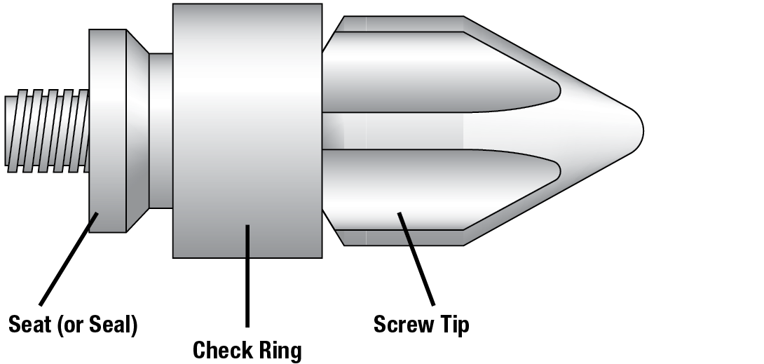
Most plastic injection molding machines use a 3-piece check ring assembly at the tip of the screw. This assembly is acceptable for non-performance PVC/CPVC applications where the polymer is not close to degradation. This screw tip assembly is often preferred for lower viscosity flexible PVC materials which tend process better with a check ring to seal and prevent back flow. The downside to this assembly is that there are multiple surfaces where the PVC may stagnate and begin to degrade. You will likely need to purge the barrel more often when processing PVC or CPVC with a check ring assembly to prevent material degradation.
When melted properly, the polymer at the front of the screw is ready to be processed. During processing, the polymer is forced to flow using pressures up to 1,500 psi (pounds per square inch) or 100 bar for extrusion and blow molding processes or 15,000 psi (pounds per square inch) or 1000 bar for injection molding processes.
Once processed into its final form, the polymer is cooled down enough to maintain its final form and function. During the cooling process, energy is removed from the melted polymer, causing the final product to shrink. In the case of injection molding, the final part will have smaller dimensions than the injection mold. In the case of extrusion, the final product will shrink in the downstream cooling system. The slower the polymer cools, the more shrinkage the polymer encounters.
Some polymers such as PVC are often processed in a vented barrel to release moisture and volatiles from the melted material. The screw used for such extruders have a vent zone which has deep flights similar in depth to the feed zone. The depth of this zone creates a low-pressure zone where the polymer stays in the barrel where volatiles can be vented through a hole in the barrel.
If material moisture is being vented, the barrel will usually vent to atmosphere, but more volatile materials like PVC will often use a filtered vacuum system to actively remove the volatiles from the barrel.
Typical 3-Piece Check Ring Assembly
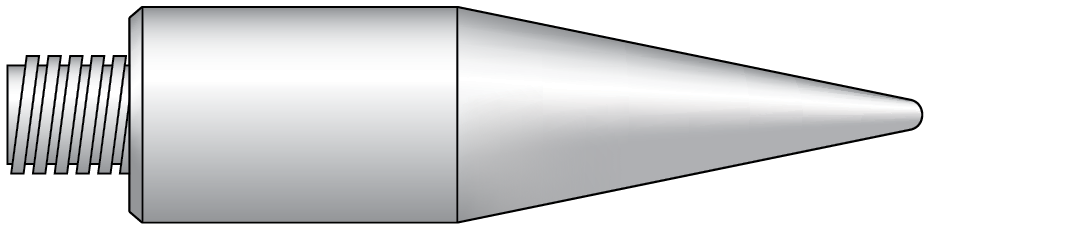
In performance PVC and CPVC molding machines, a smear tip assembly is preferred because the design is streamlined to help prevent material stagnation and degradation. The small clearance between the smear tip and the barrel walls allows the material to flow slowly forward during recovery while minimizing material backflow during injection where the flow rate is significantly faster.
Typical Smear Tip
Viscosity, Shear Rate, and Orientation
Viscosity is a measure of a polymer’s resistance to flow. Shear rate is a function of the material flow rate and the cross-sectional area of flow. Shear rate is increased by either reducing the cross-sectional area or increasing the material flow rate. With polymers, an increase in shear rate causes the polymer chains to align in the direction of flow. This alignment is called orientation. The polymer is stronger in the direction of flow due to polymer chain orientation. Slowing the product cooling with increased material or coolant temperature will reduce this orientation.
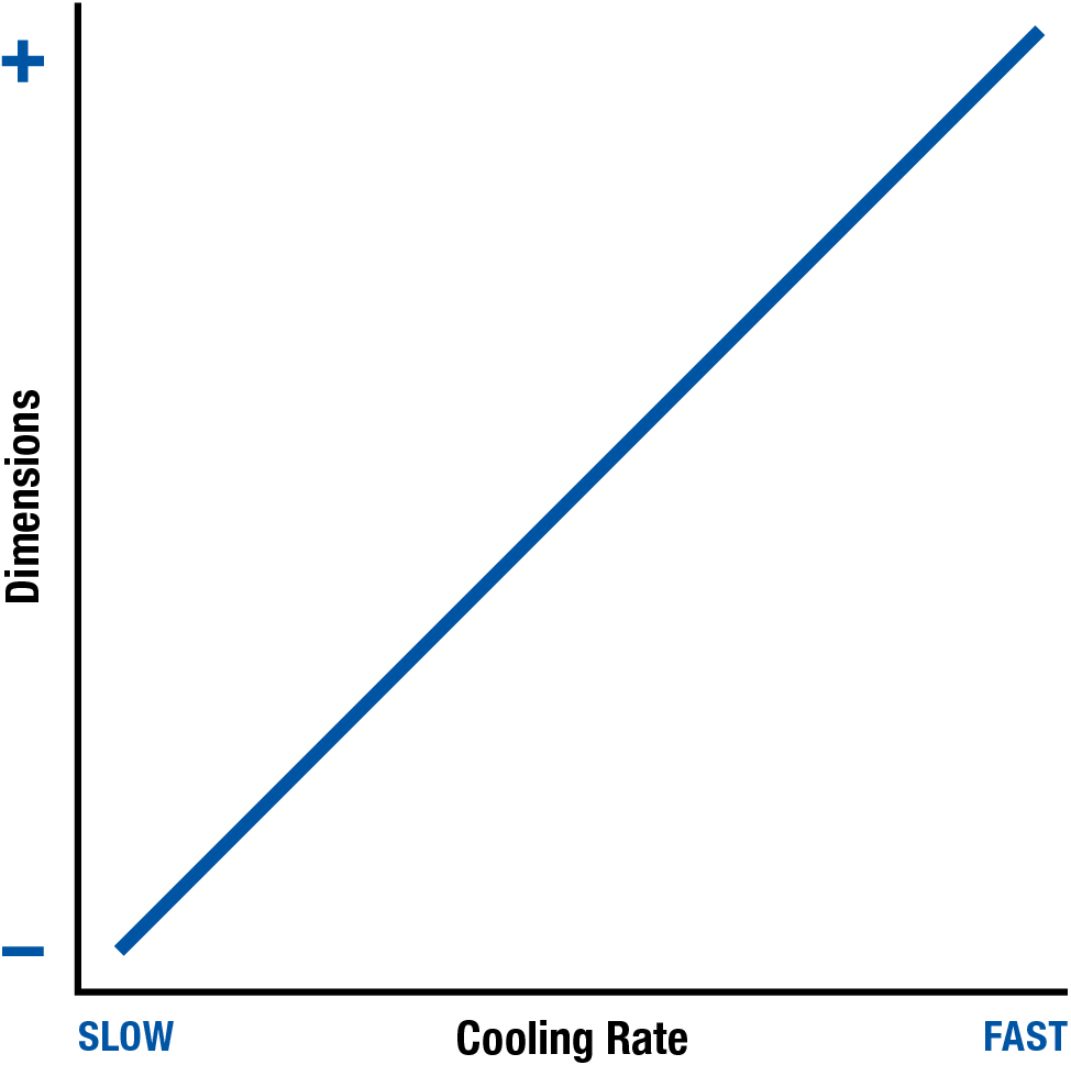
Polymer Cooling Rate
When cooled, polymers will shrink as the molecules reduce their energy level and consume less space, but the amount of shrinkage that occurs depends on the cooling rate. With all polymers, a slower cooling rate allows for more time for polymer chain mobility. This increased chain mobility allows the polymer chains to pull themselves closer together due to a large amount of intermolecular attraction.
The cooling rate is an important factor in plastic part dimensions. The slower the cooling rate, the more the polymers will have time to shrink due to intermolecular attraction. The graph below provides a basic example of how the polymer dimensions will increase with a faster cooling rate.
Cooling Rate and Part Dimensions
The hot plastic is typically cooled using water as a coolant. For injection molding and blow molding processes, this cooling takes place inside a water-cooled mold. For extrusion processes, this cooling typically takes place inside a water tank or water chilled rollers. Blown Film is one process that uses forced air as the primary method of polymer cooling. The two factors that affect Cooling Rate are temperature and cooling time.
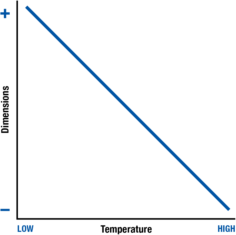
Temperature
The higher the temperature of the melted plastic or coolant, the slower the cooling rate. The rate is slower because it takes longer for the heat to be removed from the polymer resulting in smaller dimensions. Likewise, lower temperatures cause the heat to be removed faster, resulting in a faster cooling rate. In general, lower temperatures cause larger dimensions and higher temperatures cause smaller dimensions.
Temperature and Part Dimensions
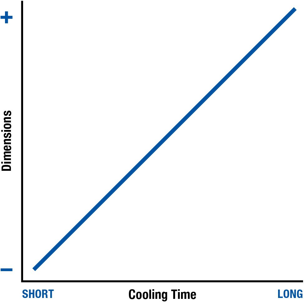
Cooling Time
The time the plastic is being cooled is the cooling time. The cooling time refers to the time when the heat is being removed from the plastic quickly. The longer the Cooling Time, the quicker the heat is being removed from the polymer. For injection molding and blow molding processes, this is the time the mold remains closed after the plastic has been forced against the mold surface. For extrusion processes, cooling time refers to the time the plastic remains in the cooling system, such as the cooling tank or chiller rollers. In extrusion, a faster line speed causes a lower cooling time.
A longer cooling time causes a faster cooling rate which results in larger dimensions. Shorter Cooling Times remove less heat resulting in a slower cooling rate and smaller dimensions. For these reasons, a longer cooling time causes larger part dimensions while a shorter cooling time will result in smaller dimensions.
Cooling Time and Part Dimensions
Basic PVC & CPVC Machinery Concerns
The chlorine present in PVC and CPVC will promote corrosion of any surface it touches. The chlorine gas which is given off when processing chlorine will promote oxidation with any metal surface it contacts.
All metal surfaces should be made of stainless steel whenever possible because of its inherent resistance to corrosion and . Corrosion-resistant coating such as chrome, teflon, rubber, plastic, or a powder-coat (similar to paint, but much more durable) tend to work very well, except they can often be removed when abraded or impacted. In many cases, processors use stainless steel with a corrosion or oxidation resistant coating to maximize the corrosion and oxidation resistance of their metals.
For process machinery, stainless steel is the preferred material for exposed surfaces such as the screw and barrel. For example, a PVC screw may be constructed from chrome and teflon-coated stainless steel with a highly-polished ‘Class A’ finish.
All surfaces where the polymer flows must be streamlined with no places where the polymer can stagnate and begin degrading. The barrel and screw surfaces should be polished to a smooth, mirror-like finish. For injection molding, the inside of the end cap and nozzle must also be polished, ensuring they are perfectly centered and aligned so the internal surfaces are smooth to the nozzle tip. For extruders and blow molders, the inside of the adaptor and die should also be polished, with all components perfectly centered and aligned to ensure smooth internal surfaces to the exit of the die.
Injection molders and blow molders will also use stainless steel molds and tie bars. Extruders will use stainless steel dies, cooling tanks, and downstream equipment. Plastic pipes and hoses with brass fittings are also common to prevent oxidation of the water system.
All exposed surfaces — including the outside of the mold or die — should be cleaned regularly with an acid neutralizer to mitigate the impact of chlorine gas and then sprayed with a surface protectant or lubricated if it is a moving part.
Quality Assurance & Quality Control
The industry trend is to move towards quality assurance (QA). However, the difference between quality control (QC) and quality assurance (QA) with respect to plastics processing, is not always clearly understood. In general, quality assurance involves producing the acceptable product using the same process each and every production run.
Although there is much more behind both quality control and quality assurance practices, this section will cover some basic concepts critical to plastics product quality. The following sections of the guide cover factors important to plastic product quality.
Subjective Quality Standards
According to the Oxford Dictionary, ‘Subjective’ is defined as ”based on or influenced by personal feelings, tastes, or opinions”. Subjective quality involves accepting or rejecting product quality based on the opinion of the person inspecting the product.
Subjective standards are those which might vary from person to person, depending on the experience and knowledge of the person inspecting the product. This typically involves determining whether the product is acceptable or rejected based on the product inspector’s opinion. Examples of subjective quality criteria include visual defects such as sinks, warpage, surface finish, shiny spots, dull areas, and scratches. With good training, experience, and knowledge of the customer’s requirements, a quality inspector can make educated decisions and determinations based on whether the product is good or bad. However, these decisions can still vary from one inspector to another.
Although there will always be the need for quality personnel to make subjective judgment calls in questionable situations, the best practice is to evaluate product to a consistent and objective quality standard each and every production run.
Objective Quality Standards
According to the Oxford Dictionary, ‘Objective’ is defined as “not influenced by personal feelings or opinions in considering and representing facts.” Objective Quality Standards involve accepting or rejecting product quality based on specific quantitative or comparative standards.
Quantitative standards are those which can be measured, such as a specific dimension, product weight, or impact strength. These standards also include quality aspects which can be measured with gauges such as a go/no-go gauge, fit gauge, colorimeter, or gloss meter. Quantitative standards can be made by different people with the expectation that they will come to the same conclusion. For example, if the acceptable dimension is 3.000mm +/- 0.020mm, then anyone encountering a measurement of 3.005mm would agree the dimension is within specification. Advanced quality standards such as Geometric Dimensioning & Tolerancing (GD&T) provide methods for quantifying complex measurements such as surface, flatness, concentricity, and maximum or minimum material conditions. GD&T measurements are typically measured using advanced equipment such as a Coordinate Measuring Machine (CMM), which can take many measurements while using a computer to quantify the measurement objectively.
Objective quality standards apply not only to the product being inspected, but also to the process used to manufacture it. For example, the process itself can have maximum and minimum limits on injection pressure, material temperature, back pressure, weight, mold coolant temperature, dimensions, and cycle time. Some of these limits can be monitored directly by the machine controls, others must be measured with a temperature probe or weighing scale. Plastics processors who provide true quality assurance to their customers have systems in place to ensure that both the product and the process remain consistent from run to run.
Objective quality standards help ensure the technician can produce product the customer will find acceptable — each and every production run.
Quality Control
For plastics processing, quality control involves inspecting product during first piece approval and during production to prevent defects from getting to the customers. There are many quality strategies focusing on how much product is inspected at specific intervals, most of which are designed to balance the risk of bad product getting to the customer with the cost associated with product inspection. In general, the goal of quality control is to create inspection systems to prevent bad or faulty product from reaching the customer. Statistics and proper inspection strategy can significantly improve the effectiveness of your quality control systems. Aside from routine inspection, quality control does not take any steps in preventing bad product except through first piece approval at the start of a production run.
Quality control is always a key aspect to customer retention since it can be devastating when the customer receives bad product, but it is not a substitute for effective quality assurance techniques. In general terms, quality control is focused on preventing bad product from reaching your customer, but not ensuring that there is consistency when a product is manufactured by the production machinery.
Quality Assurance
For plastic processing, quality assurance starts with making acceptable product that conforms to objective quality standards with process which conforms to the approved documented process. In practice, this involves verifying both the product meets objective quality standards and the process conforms with the approved process sheet. This dual product and process approval should take place at first piece approval, at pre-determined time intervals, and after any significant change is made to the process. Significant changes include a material lot change, adjustment to regrind percentage, color change, machinery repair, or equipment change.
If acceptable products are being produced with an approved process during every production run, then quality has a high level of confidence that the customer is receiving quality products over time. This is the foundation of Quality Assurance for plastics processors. With most plastics, following the entire process sheet for every production run helps maintain strong process consistency.
Quality Assurance for PVC & CPVC
With respect to PVC and CPVC, the process-specific documentation portion of the process sheet should be duplicated each and every time. On every production run, the product should have the same cooling time, short shot weight, packing pressure, etc., as these parameters do not have a significant effect on gelation or fusion of performance PVC/CPVC. In this case, quality assurance involves making sure these remain the same every time the process runs, regardless of the shift personnel.
With PVC and CPVC, the run-specific documentation portion of the process sheet should be duplicated whenever the source materials are similar. When the source material is different, these may be adjusted to achieve the proper time, temperature, and shear balance complication to reach the amount of gelation or fusion required to meet end-use requirements
For performance PVC/CPVC, you may need to reduce the material temperature or back pressure to compensate for a material lot that degrades easily or was dried twice. Conversely, you may have a part that is visually acceptable but is failing performance testing. A rise in material temperature or back pressure could be helpful in increasing the amount of gelation or fusion in your final performance PVC/CPVC product.
The more documented history you have from your material suppliers, the more likely you will be able to compensate for these changes. When possible, work with your PVC/CPVC supplier to obtain more consistent source material over time.
Scientific Documentation
Documentation Concerns
With performance PVC & CPVC, all components are not fully mixed before processing. During processing, these components are further combined into a polymer matrix, which is often referred to as a gel. The combination of these components is referred to as gelation or fusion. Full gelation is the point where the polymer matrix or gel has fully formed, and the polymer achieved its optimal strength and resistance properties. Performance PVC & CPVC applications are those which need a high percentage of gelation in the final part to meet end-use requirements.
The amount of time, temperature, or shear required to reach full gelation of your PVC or CPVC will vary depending on many factors. A change in material supplier, material blending equipment, or pelletizing equipment will vary the time, temperature, and shear history of your source material. A change in processing equipment, auxiliary equipment, or drying equipment will change the time, temperature, or shear history of the polymer. These differences in source material may require process changes to ensure the final part meets end-use requirements. For more on the above, please review the ‘Time, Temperature, and Shear’ chapter of this reference guide.
The more material and process information you can document for each production run, the better you can identify these changes when they occur. With the right information, you should be able to accommodate source material changes with your process.
In this chapter, we will review the 3 primary forms of documentation, as well as process calculators used for documentation:
- Setup Sheet
Document process inputs - Process Sheet
Document process outputs (standard and run-specific) - Process Change Log
Document all process changes
Process Inputs vs. Process Outputs
Process inputs are the machine-dependent parameters entered into the processing equipment. These settings include parameters such as: injection speeds, barrel temperatures, and transfer position.
Process outputs are machine-independent, process-specific parameters, which result from the process. These outputs include: temperatures, pressures, weights, times, as well as any additional information important to the product or process. Additional information which are also considered process outputs include: part measurements, material dewpoint, quality information, clamp tonnage, photographs, and observations.
Open Loop vs. Closed Loop Process Controls
Open loop process control systems guide the process through a series of predetermined steps. After the process is complete, the cycle starts over again. As the process is in operation, the operator is left to examine the process outputs for inconsistencies. The operator is then responsible for correcting the process for inconsistencies. The more inconsistent a process is, the harder it becomes for the operator to correct. The accuracy of an open loop process is solely dependent on the knowledge and experience of the operator.
Closed loop process control systems are designed to automatically correct variations in the process. Electrical measuring devices, such as pressure gauges, are used to measure the process outputs. A feedback loop is used to transfer process outputs to the closed-loop process control system. A microprocessor is then used to evaluate the process outputs for variations. The microprocessor compares the actual process outputs to the desired process outputs. If a variation is detected, the microprocessor determines how much of a particular action is required to correct the process. The signal is then sent back to the equipment, and the process is adjusted. The quick response of closed-loop process control systems makes them effective in controlling and reducing variations within a process.
Machine Documentation: Setup Sheet
Each molding machine will have its own documented set of process inputs, which is typically referred to as a Setup Sheet. Setup sheets are a record of the process inputs or settings which make a good product. This machine-specific documentation is very helpful to technicians when installing and setting up the machinery.
The setup sheet should include critical information about the specific run, and should be obtained each time the process achieves the first-piece approval. This sheet should contain general information, as well as machinery settings.
The following sections detail common information that can be recorded on each section of the Setup Sheet.
General Information
- Date & Time
- Material Type, Grade, and Lot #
- Material Supplier
- Blending Plant & Line
- Pellitizer Plant & Line
- Regrind, Additives, & Colorants
- Source
- % Used
- Mold, Machine, Auxiliary, & Downstream Equipment
- ID, type, & condition
Molding Machinery Setpoints
- Injection *
- Times: Delay and Maximum
- Max. Pressure
- Speed
- Positions: Shot Size and Transfer
- Packing *
- Time
- Pressure
- Speed
- Cooling
- Time
- Temperature: A-side, B-side, and other setpoint(s)
- Cooling Line Layout Diagram
- Recovery
- Times: Delay & Maximum
- Back Pressure
- Speeds: Decomp. Before, RPM, and Decomp. After
- Temperatures: Feedthroat, Barrel, and Nozzle
- Positions: Decomp. Before, Shot Size, and Decomp. After
- Mold Open
- Times: Delay & Maximum
- Speeds: Breakaway, Fast, and Final
- Positions: Breakaway, Fast, and Fi
- Forces: Breakaway, Fast, and Final
- Ejection Forward
- Times: Delay and Maximum
- Speeds: Slow and Fast
- Positions: Slow and Fast
- Ejection Retract
- Times: Delay and Maximum
- Speeds: Fast and Slow
- Positions: Fast and Slow
- Mold Close
- Times: Delay, Maximum, Protect, and Tonnage
- Speeds: Fast, Slow, and Protect
- Positions: Fast, Slow, and Protect
- Forces: Fast, Slow, Protect, and Tonnage
- Upper & Lower Process Limits
- Alarms for All Critical Parameters
- All Auxiliary & Downstream Equipment
- All Setoints and Configuration
- Pictures (when possible)
NOTES:
* If profiling is used, be sure to include multiple values — and a photograph of the profile curve, if possible.
Process Documentation
Each Mold or Product should have its own set of process outputs, typically referred to as a Process Sheet. Process sheets are a record of the actual process that made a good product. This process-specific documentation is very helpful to technicians when starting up and troubleshooting the process. There should be an approved standard process sheet used as a reference during each production run, as well as run-specific process sheets filled out during each first-piece approval.
Process Process Sheet: Process Outputs
Each Mold or Product should have its own set of process outputs, typically referred to as a Process Sheet. Process sheets are a record of the actual process that made a good product. This process-specific documentation is very helpful to technicians when starting up and troubleshooting the process. There should be an approved standard process sheet used as a reference during each production run, as well as run-specific process sheets filled out during each first-piece approval.
The process outputs shown here should be consistent from one production run to another, regardless of the machine and auxiliary equipment used. If a future machine or piece of auxiliary equipment is incapable of performing as documented, it should not be used to manufacture that product, as it will not be able to duplicate the documented standard.
The following are examples of common process outputs and information that can be obtained:
- Injection *
- Time
- Pressures: Peak and Transfer
- Short Shot Weight (and photo)
- Packing *
- Time
- Pressure
- Final Part Weight
- Cooling *
- Time
- Temperature
- Pressure
- Flow Rate
- Cooling Line Layout
NOTES:
The entire shot should be weighed at transfer and after packing, but the individual cavity weights can also be documented for additional information for multi-cavity molds.
*If profiling is used, be sure to include multiple values — and a photograph of the profile curve, when possible.
*Be sure to include values both to and from the process for each controller — and note the number of cooling line loops, if applicable
Process Sheet: Run-Specific Documentation
Time, Temperature & Shear Considerations
- Primary Time Considerations
- Cycle Time
- Estimated Barrel Residence Time
- Regrind Percentage
- Secondary Time Considerations
- Dryer Residence Time
- Material Moisture Content
- Smear Tip Utilized (YES/NO)
- Primary Tempertaure Considerations
- Material Temperature Measurement
- Screw Cooling Utilized (YES/NO)
- Screw Coolant Temperatures: To and From Process
- Barrel Cooling Fans Utilized (YES/NO)
- Barrel Zone Temperatures (actual)
- Secondary Temperature Considerations
- Dryer Temperature
- Hot Runner Temperatures: Actual Temps
- Primary Shear Considerations
- Back Pressure
- Recovery Time
- Injection Time
- PVC-Specific Screw Utilized (YES/NO)
- Gelation or Fusion Test Results
- Testing Results (PASS/FAIL)
- Testing Measurements: Actual Data
Barrel Residence Time Calculation
There are many techniques for estimating the barrel residence time, but the easiest is to start from the assumption that the screw holds approximately 2 times the maximum shot size in the barrel.
Calculation Notes:
Estimated # Cycles in Barrel =
(Estimated Barrel Capacity ÷ Part Shot Size)
Estimated Barrel Residence Time Calculator
Dryer Residence Time Calculation
To determine the Dryer Residence Time, you must first determine the Dryer Capacity. Keep in mind, dryers are rated for polystyrene which has a specific gravity of 1.0. Therefore, you will have to adjust the capacity for the specific gravity of your material.
Calculation Notes:
- Dryer Capacity = Amount of material the dryer can contain in polystyrene
- Specific Gravity = Specific gravity of your material
- (Dryer Capacity ÷ Output Rate) = Estimated Dryer Residence Time
Estimated Dryer Residence Time Calculator
Scientific Molding
Scientific Molding involves using the best practices and process data to develop a robust and reliable molding process. This chapter covers best practices for developing a Scientific Molding process for PVC and CPVC.
Gelation Concerns for Performance PVC & CPVC
With performance PVC & CPVC, all components are not fully mixed before processing. During processing these components are further combined into a polymer matrix, which is often referred to as a gel. The combination of these components is referred to as gelation or fusion. Full gelation is the point where the polymer matrix or gel has fully formed and the polymer achieved its optimal strength and resistance properties. Performance PVC & CPVC applications are those which need a high percentage of gelation in the final part to meet end-use requirements.
Too little time, temperature, or shear will result in insufficient gelation and thus poor performance of the final part. Too much Time, Temperature, or Shear can cause degradation of the PVC. Good PVC processing is based on understanding and balancing time, temperature, and shear. For more on the above, please review the ‘Time, Temperature, and Shear’ chapter.
Injection
In Scientific Molding, Injection uses screw velocity to control the viscosity of the polymer being injected into the mold.
Injection Speed
Since the higher viscosity PVC or CPVC encounters high shear rates when it enters the gate, a low injection speed is commonly used in the gate area. This low injection speed causes a large increase in material viscosity, making it very difficult to fill the whole mold. To decrease the viscosity of the PVC or CPVC during injection, a higher injection speed is typically used while filling most of the mold cavity.
Keep in mind, high injection speeds also increase shear on the polymer, but this shear is very quick. Shear during injection does not have a significant impact on the mixing of performance PVC or CPVC polymers with respect to improving gelation. High injection speeds can cause over-shearing and degradation of the PVC or CPVC. Low injection speeds will increase the polymer viscosity, which can prevent mold filling or packing.
Injection Speed Profiling
Although most polymers mold well with one injection speed, PVC & CPVC often process better with multiple injection speeds. The easiest way to determine the preferred injection speeds is to conduct an injection speed study with packing turned off. An Injection Speed Study involves creating short shots with 5 to 10 different injection speeds. The parts produced are labeled with the Injection Speed and evaluated to determine which speeds look the best in the runner, gate, middle, and end, as well as any concern areas. These typically indicate what speeds are best in what areas.
For example, suppose an injection speed study determined the gate area looks best at 0.2 in/s (5mm/s), but the rest of the part looks good at 0.6in/s (15mm/s). In this case, the best starting point when developing the injection profile would be using 0.2in/s & 0.6in/s (5 & 15mm/s). If the short shot looks good in all areas at one speed, such as 0.4in/s (10mm/s), then you should use just one injection speed to mold the part.
When establishing the profile, you will need to conduct short shots at each stage to determine when each area is filled so you can begin the next injection speed. Ensure the transfer position for the first speed selected passes far enough beyond the area of concern before transferring to the next speed. You will need to document the time, pressure, and short shot weight at each transition to be able to properly repeat your profile during startups and troubleshooting.
The advanced method for Injection Profiling is to conduct a Rheology Curve at 10 different injection speeds while collecting and labeling the short shots for an Injection Speed Study. Although PVC and CPVC have very high viscosities, the polymers still show shear thinning behavior as the injection speed increases. When evaluating the viscosity curve, if no significant shear thinning is seen, then the gate is likely too large to cause adequate shear thinning during injection – such a large gate may make it very difficult or impossible to fill and pack the part properly. If the Viscosity Curve shows immediate shear thinning and the part shows evidence of excessive shear in the gate, then the gate may be causing too much shear because it is too small. The injection speed or speeds would be selected in the same manner as the speed study, but the advanced method allows the gates to be evaluated as appropriate or inappropriate for the application.
Maximum Injection Pressure
When injecting, is it very important to ensure you have adequate injection pressure available to avoid a pressure-limited process. A pressure-limited process is one where the maximum injection pressure is reached. This situation prevents the desired injection speed from being maintained – this causes the screw to slow down during injection. Since the screw speed during injection controls the viscosity of the polymer, injection speed control is very important for PVC and CPVC. A pressure-limited process causes a slowdown of the screw, resulting in an increase in polymer viscosity. This causes a significant pressure loss, which may prevent the part from being injected or packed completely.
During process development, a high injection pressure should be used to allow for changes in speed to not cause the process to become pressure-limited. This allows the process developer to conduct the necessary studies and create the correct injection profile.
Once the process is being prepared for production, the max injection pressure should be set to 20% above the peak injection pressure. Too much pressure during production can cause excessive pressure to build up if a flow obstruction, such as a blocked cavity, occurs. This high pressure can often cause significant mold damage. Too little injection pressure available during production can cause the process to become pressure-limited, which will cause variation and defects, such as shorts, sinks, and voids.
Maximum Injection Time
When injecting, is it very important to ensure you have adequate injection time available to ensure the process injects until it reaches the transfer position.
During process development, a high injection time should be used to allow for changes in speed to not cause the process to stop injecting prematurely. This allows the process developer to conduct the necessary studies and create the correct injection profile.
Once the process is being prepared for production, the max injection time should be set to 20% above the injection time. Too much time available during injection can cause pressure to be applied for excessive periods of time if a flow obstruction, such as a blocked cavity, occurs. This situation can often cause mold damage. Too little injection time available during production can cause the process to transfer prematurely, which can cause variation and defects such as shorts, sinks, and voids.
Transfer Position
The transfer from injection to packing should take place when all mold cavities have a short shot. When developing the transfer position, the part should be considered 100% injected when the first mold cavity is full (or the flow is stopped by a gas trap). At this point, all the mold cavities should be weighed, and this should be documented as the part weight at 100% full. Multiply the full injection weight by 90 and 95% to calculate the desired part weight range at transfer. The transfer position should be adjusted to get an injection weight between this 90 and 95% full range. This transfer position ensures all cavities remain short shot at the time of transfer during normal variation.
If all the mold cavities are not short at transfer, then they will start to pack during injection, causing variation in the process. Since PVC and CPVC tend to be injected very slowly, the process can be easily affected by small shifts in viscosity. It is always recommended to have all the mold cavities short to ensure normal variation does not significantly affect the process and cause packing to occur during injection.
Packing
The purpose of Packing is to complete mold filling and compensate for material shrinkage so that the part best represents the features of the mold.
Packing Pressure
The packing pressure must be high enough to fill & pack the part without flashing or over-packing the mold. Although your molding machine may be capable of utilizing multiple 2nd stage packing pressures, you should only apply a single pressure setting until the end of packing. Using one packing speed makes the process more repeatable with less variation.
To determine the appropriate packing pressure, you should determine the minimum and maximum packing pressure, which provides an acceptable packed-out part. With PVC & CPVC, it is best to start the lab with times currently in use with similar processes. If you are unsure as to what packing time to start with, it may be best to perform the 2nd stage packing pressure study at 2 or 3 different packing times.
This acceptable packing pressure range (minimum to maximum acceptable packing pressure) is your process window. Select a final packing pressure in the middle of this range. If the process window is large, the process should be easy to maintain over time. If the window is small, the process will be very difficult to maintain, thus some parameters, such as temperature, injection speed, or packing time, might need to be changed to obtain a larger process window.
Packing Speed
Most molding machines allow you to select a packing speed. This packing speed should be set to the same speed as your injection speed. If you are using multiple injection speeds, the packing speed should be set to the last speed in your profile. Using the same speed when packing allows the screw to slow down naturally. If a different speed is used, the screw may speed up or slow down at transfer, which may cause defects such as shorts or flash.
Packing Time
For most non-PVC or CPVC applications, the gate will seal or freeze off during 2nd Stage Packing. When the gate seals, it prevents material from flowing in and out of the mold cavity when packing pressure is turned off.
Many PVC and CPVC materials have very high viscosities that require very high injection pressures using very large gates. Many of these large gates require such a long time to achieve gate seal that it is unprofitable to wait for gate seal to occur when molding PVC and CPVC parts.
For PVC parts, longer packing times will tend to provide a better-formed and packed part, but lower packing times will save cycle time and reduce part weight. Packing time studies on PVC parts involve molding parts at different packing times and evaluating them for part quality, as well as weighing them for material consumption. If the part weight does not increase and the part achieves gate seal, then select a time after gate seal as your packing time. If the part does not show a gate seal, find the packing time range that provides a good product and run the process near the middle of this time.
Keep in mind, as you increase packing time, you will need to reduce the cooling time to maintain the same balance of time, temperature, and shear during the packing time study. For more about the time, temperature, and shear balance, please review the relevant chapter in this guide.
Clamp Tonnage
PVC and CPVC have high viscosities and typically require a large gap in the parting line or mold damage for flash to occur. Too low a clamp tonnage will allow flash to occur. Excessive clamp tonnage causes excessive wear to mold components, as well as block vents causing burning or dieseling.
A clamp tonnage study is the best way to determine the minimum amount of tonnage necessary to prevent flash. To conduct this study, mold a good part and document the clamp tonnage. Then gradually reduce and document the clamp tonnage until the bad parts are produced. Lastly, add 10% tonnage to the minimum tonnage that makes an acceptable product. This is your recommended clamp tonnage.
Multi-Stage Packing for Pressure-Sensitive Molds
In a small percentage of molds, the packing pressure required to complete filling can cause defects in the molded product if one packing pressure is used. If a mold cannot be processed with a standard 2-Stage Scientific Molding Process, then a multi-stage packing approach can be used.
The initial packing stage is determined by conducting a DOE (Design of Experiments) with multiple packing times & pressures to create a packing window where the mold cavity is filled, but the over-packing defect is not present. Once this window is created, select a packing time and pressure in the center of this window. This initial packing time and pressure should consistently fill the mold cavities, while not over-packing the part.
Initial Packing Window for Multi-Stage Packing
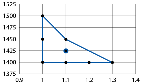
The final packing pressure and packing time are determined in the same manner as mentioned in the preceding sections.
Screw Recovery
Screw recovery is very important to the melting & preparation of your PVC or CPVC. Recovery is also the most important factor concerning the time, temperature, and shear impact on the gelation of performance PVC and CPC polymers. When processing PVC/CPVC, it is always best to use barrel heaters equipped with integrated cooling fans to remove heat from the barrel when needed. When processing PVC on larger molding machines, a screw cooling system is best to prevent excessive heat in the polymer during recovery.
PVC and CPVC are typically processed at plastic temperatures between 325-400°F (160-205°C).
Because degraded PVC/CPVC can rapidly cause a chain reaction of degradation, you should always avoid excessive temperatures or back pressures. Barrel and screw cooling are very helpful in reducing this heat generation. Temperatures for PVC and CPVC should always be increased at a moderate pace to allow adequate time for the process to stabilize.
If the polymer ever starts to degrade when processing, it is best to purge the barrel with a heat-stable polymer as soon as possible. It is always important to remove degraded PVC or CPVC from the barrel immediately to prevent a dangerous degradation chain reaction from occurring.
Screw Delay or Decompression Before Recovery
Immediately after packing, there is a large amount of pressure present in front of the screw. This back pressure must be relieved or the screw will be subjected to the force of packing at the same time it is subjected to the torque of packing during recovery. This combined force & torque puts a large strain on the screw, which can cause the it to break or bend during recovery. If this pressure is not relieved, the PVC or CPVC will also be subjected to a brief moment of extremely high shear when the screw begins to turn. This short period of high shear will contribute to the degradation of your PVC or CPVC.
Screw delay before recovery is the most common way to relieve the pressure in front of the screw before recovery. This option uses a recovery delay, such as 0.2 seconds, to allow the pressure in front of the screw to be relieved by pushing the screw back before recovery starts.
Screw decompression pulls the screw back a short distance to reduce the packing pressure before recovery. This method is not recommended for PVC and CPVC as decompression before recovery might create a negative pressure. If the gate is not sealed at the end of packing, screw decompression may pull the polymer out of the mold cavity and into the runner system, causing defects such as sinks or voids near the gate.
Screw RPM
With most materials, it is preferred to complete screw recovery in 80% of your cooling time when possible. Since PVC and CPVC are very shear sensitive, most molders reduce shear with a lower screw RPM. If screw recovery exceeds the cooling time, the screw will extend the cycle time until the shot is recovered. This should be avoided, as longer cycle times can contribute to the degradation of your PVC or CPVC. It is important to ensure your screw recovery consumes no more than 95% of your cooling time for PVC/CPVC.
The primary purpose of Screw RPM is to turn the screw fast or slow enough to achieve your intended recovery time. If the PVC or CPVC process needs more heat, the barrel temperatures should be raised. If more shear is needed in the plastic, back pressure should be increased.
If necessary, you will need to extend your cooling time to ensure you have a consistent cycle time which is not affected by your screw recovery. To calculate the maximum screw recovery time, multiply your cooling time by 0.95.
Barrel Temperatures: Rear Half
For PVC or CPVC, the rear half of the barrel should use a lower temperature in the rear zone. The zone temperatures should increase incrementally to the front half temperatures. In general, a low rear zone temperature improves the conveyance of PVC or CPVC powders, pellets, or regrind in the feed zone of the screw. Increasing temperatures in the middle zones help the polymer melt begin melting as the screw channel depths decrease. You should avoid high temperatures in the rear zone, as PVC and CPVC prefer to be heated gradually during recovery.
A rear half temperature study is used to determine the rear zone temperature, which provides the best material conveyance and recovery. Before starting this test, start with a moderate rear-half temperature and stabilize the process. Once the process is stabilized, record the rear zone temperature and screw recovery time. Incrementally reduce the rear-half temperatures, stabilize the process, and document the recovery time. The optimal rear-half temperature profile is the one that provides the best recovery time while still making acceptable parts.
Barrel Temperatures: Front Half
Since the polymer heat history is important to both gelation and degradation of performance in PVC or CPVC materials, the zones in the front half of the barrel should all be set to the same temperature. This straight profile in the front provides the most consistent control of the material temperature during recovery. These front-half temperature zones should be raised or lowered together to ensure accurate control of the polymer temperature.
Barrel Temperatures: Barrel Temperatures: Nozzle &ano; End Cap
The nozzle and end cap do not influence material melting. Therefore, these zones should be increased or lowered to compensate for cycling issues. For example, these temperatures may need to be lowered to correct for heat issues, such as drooling or degradation. These temperatures may need to be increased to compensate for cycling issues such as a stuck sprue or blocked nozzle.
Back Pressure
Back pressure forces the screw to pump harder to force plastic to accumulate at the front of the screw. Increasing back pressure puts work and energy into the plastic, which increases the shear applied to the polymer. This increase in energy applied to the PVC also increases the temperature of the PVC or CPVC material. Back pressure should only be increased when more material mixing is needed or when more shear is needed to reach peak gelation in performance PVC/CPVC applications.
Adding back pressure slows the pumping of material to the front of the screw, thus, screw RPM will also need to be increased to maintain your desired recovery time. Always add back pressure incrementally, allowing the process to stabilize at each step to help avoid a dangerous chain reaction of PVC or CPVC degradation.
Screw Decompression After Recovery: Check Ring Machines
Injection molding machines equipped with a check ring require decompression after recovery to relieve pressure on the check ring after recovery. This pressure relief ensures the check ring will seat properly when the screw begins to move forward during injection. Without screw decompression, check rings will provide an inconsistent injection from shot to shot. Check rings are not recommended for processing PVC and CPVC, as they have additional surfaces where polymer flow can easily stagnate and cause degradation. Smear tips are the preferred screw tip for processing PVC and CPVC because they have a streamlined design that does not allow the polymer flow to stagnate.
Screw Decompression After Recovery: Smear Tip Machines
Injection molding machines equipped specifically for PVC or CPVC will have a smear tip at the end of the screw. The smear tip design allows for smooth material flow around the tip of the screw without any material stagnation. The smear tip does not need decompression after recovery to ensure a consistent injection from shot to shot. Some molders may use a small amount of decompression after recovery to help reduce material drooling and stringing when the mold opens for part removal.
Cooling
When cooled, polymers will shrink, but the amount of shrinkage that occurs depends on the cooling rate. With PVC & CPVC, a slower cooling rate allows for more polymer chain mobility. This increased chain mobility allows the polymer chains to pull themselves closer together due to a large amount of intermolecular attraction. This results in increased polymer shrinkage. The cooling rate is generally the most important factor in plastic part dimensions. The slower the cooling rate, the more the polymers will shrink due to intermolecular attraction. The 2 factors that affect the cooling rate are coolant temperature & cooling time.
PVC and CPVC are typically processed using coolant temperatures between 60-130°F (15-55°C).
Coolant Temperature
The heated PVC or CPVC polymer is cooled using water as the coolant. The higher the coolant temperature, the slower the cooling rate since it takes longer for the heat to be removed from the polymer. For this reason, a higher coolant temperature causes smaller part dimensions while a lower coolant temperature cooling time will result in larger dimensions.
Temperature vs. Part Dimensions
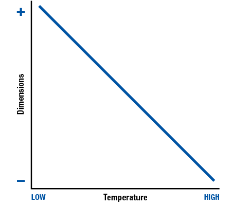
Cooling Time
For Injection Molding, cooling time is the time the mold remains closed, and the coolant removes heat from the polymer. The longer the cooling time, the quicker the heat is being removed from the polymer. This results in a faster cooling rate. Shorter Cooling Times remove less heat from the polymer, resulting in a slower Cooling Rate. For these reasons, a longer cooling time causes larger part dimensions, while a shorter cooling time will result in smaller dimensions.
Cooling Time vs. Part Dimensions
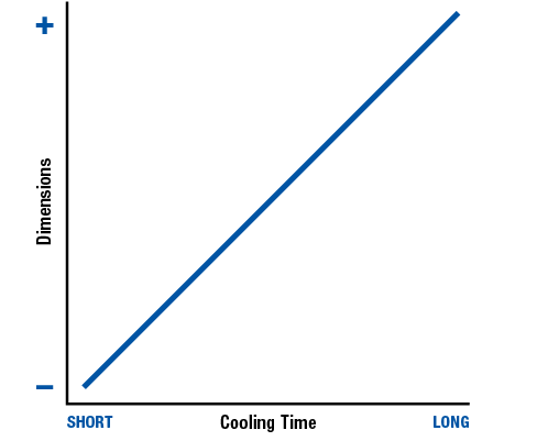
Basic Cooling Time & Coolant Temperature Study
For PVC and CPVC applications, the most common approach is to first determine the lowest mold temperature which produces good parts. Next, the lowest cooling time is determined and 10% cooling time is added for safety. If these final parts meet specifications, it is a considered a good process.
Advanced Cooling Time & Coolant Temperature Study
If the final parts from the basic study do not meet specifications, a basic Design of Experiments (DOE) should be conducted. In this scenario, parts are produced at mutiple coolant times and temperatures.
The low values in the study should represent the minimum coolant temperature and cooling time that produced an acceptable part.
A 2-factor DOE is most common when the part is already close to the desired final dimensions. A 3-factor DOE is more suitable when the part is not close to the desired dimensions. If, at any point in the study, degradation occurs, stop the study and thoroughly purge the barrel.
Basic 2-Factor Coolant Temperature & Cooling Time DOE
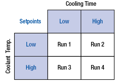
Basic 3-Factor Coolant Temperature & Cooling Time DOE
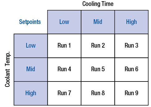
Part Removal
When establishing all mold opening, closing, ejection, and clamping functions, it is important that each motion is smooth and precise. Awkward or irregular movements, such as an ejector plate sticking or a platen bouncing, could indicate machine or mold issues. Such irregularities should be addressed immediately before putting the process into production.
Mold Breakaway
As the mold initially opens, it is known as ‘breakaway.’ It is important to determine a safe speed at which the mold halves can separate safely without damaging the part. In most cases, the slower the mold opens, the better the cavity separates from the part, but this is not always the case. For this reason, start with a slow speed, and then increase it until you determine a breakaway speed that is faster and yields acceptable parts. This breakaway speed should end when the part separates from the mold cavity, the leader pins are completely out of their bushings, and any slide-actuating pins are no longer engaged.
Mold Open Fast
After the part and leader pins are cleared, a significantly higher mold opening speed should then be used until the final mold opening distance is reached. This speed should be one that the machine can handle smoothly without causing the machine to shift during mold opening. In some cases, you may need to use a slower third mold open speed to help the mold stop at a precise location for robotic part removal.
Mold Open Distance
The final mold opening distance should be what is necessary to safely remove the part from the mold during part ejection. Every additional inch or centimeter of mold opening can consume a large amount of energy and time over the course of time. For example, if a mold opens one inch (2.5 centimeters) more than required, it will travel an additional three miles (5 kilometers) beyond what is necessary after one hundred thousand cycles. All this wasted travel consumes energy and increases wear on the platens, tie bars, and foot plates.
Eject on the Fly
Whenever possible, initiate the part ejection as the mold opens. This is often referred to as ‘eject on the fly.’ This reduces the overall time required to remove the part from the mold. The eject-on-the-fly process should not start until the mold has opened the same distance as the ejection travel. This ensures there is no way the ejector pins can touch the opposite side of the mold if a mistake is made.
Ejection Cycles
Many injection molders cycle the ejection system multiple times. The intent is to ensure all the parts are off the mold before the mold closes, but in practice, this wastes time, energy, and reduces the life of your ejection components. For example, if the ejection cycle takes 3 seconds, using 2 extra ejection cycles will consume over 160 hours after 100,000 cycles. You should cycle the ejection system only once. If multiple ejection cycles are required to remove the part from the mold, then a change to the ejection system should be done to improve this situation, as this can save hundreds of hours of production over the life of the mold.
Ejection Profiling
Since fast ejection speeds can damage the part, many injection molders will use multiple ejection speeds. The initial ejection speed should be slow enough to prevent part damage. This initial speed should continue until the part is separated from the core. The second, faster ejection speed should be used to push the part away from the core to aid in part removal. Using multiple ejection speeds can help save many seconds per cycle.
Ejection Retract
To save time, the ejection retract speed should be as fast as the machine can perform smoothly. The ejection should retract immediately without any delay to help separate the ejector pins of the plate from the part. Delays in ejection retraction should only be used if a robot or machine operator is being used to remove the part from the ejector system.
Initial Mold Close Speed
As the mold closes, the initial speed should be moderately fast. This mold closing should stop just before any mold components, such as leader pins or slides, interact.
Mold Close Slowdown
Prior to any mold component contact, the mold should slow down to a lower speed. This helps ensure components, such as leader pins, engage properly.
Mold Protect
Immediately before the mold is closed, the closing speed should go into ‘mold protect mode.’ In this mode, the clamp is closed very slowly under low force. This setting should be tested by placing a business card or a piece of cardboard between the mold halves. If mold protection prevents the mold from clamping on an obstruction, the mold protection is properly set. If the mold protection allows the mold to close up on an obstruction, it is improperly set and must be adjusted.
General Rules for Processing
When setting up or maintaining a process, there are five general rules to follow to ensure optimum results.
Rule 1: Make one process change at a time
Once the initial process parameters are entered, adjust only one aspect of the process at a time. When a change is made, it’s imperative to wait for the results to take place before making another adjustment. This rule ensures you know the specific cause and effect of any change made to the process.
Rule 2: Make significant changes
Make sure any change to the process is large enough to make an observable effect. If an adjustment is too small, it may not affect the process enough to make a logical judgment. For example, a 3° drop in coolant temperature may not produce a visible change, but a 10° or 20° change could completely resolve the issue.
Rule 3: If a change does not help, change it back
Once you’ve determined a change was ineffective, return that process parameter back to where it was. Otherwise, you may cause new defects later on. Remember that each change to the process will slowly shift the parameters away from the initial process.
Rule 4: Document the process
Once a process is established and approved, document the process. Many companies have an initial setup sheet used to get the machine started, but do not document the processing conditions at the time of first piece approval. If the approved process is not documented, the technicians may not have enough information to make accurate decisions. Be sure to document both the process inputs that are entered into the machine AND the outputs that result from the process.
Rule 5: Document all changes to the process
Once the initial process is documented, all parameter changes and their associated results must also be accurately documented. The purpose of documentation is to have an accurate record of the changes made to the process and the results of the changes. Good documentation is critical to scientific troubleshooting. In order to make logical decisions, a processor must have access to relevant information.
Scientific Troubleshooting
Scientific processing involves developing an acceptable process and, once approved, thoroughly documenting this process. This approved process documentation must be used during startup and troubleshooting to best match up the process with the standard.
Process Development
This section reviews the most important factors in developing a good Scientific Molding process, including:
- Injection
- Packing
- Recovery
- Cooling
- Part Removal
Process Documentation
The more material and process information you can document for each production run, the better you can identify these changes when they occur. With the right information, you should be able to repeat the product from previous runs with similar process settings. Much of this is covered in the ‘Scientific Documentation’ section of this guide.
Proper documentation will help technicians conduct startup and troubleshooting events with a much higher level of confidence.
Proper documentation will help technicians conduct startup and troubleshooting events with a much higher level of confidence.
Your standard process documentation should include the following:
- Setup Sheet
Document process inputs - Process Sheet
Document process outputs - Process Change Log
Document all process changes
For Performance PVC and CPVC products, it should also include run-specific documentation.
Initial Troubleshooting
When a defect is found, thoroughly review the product for all defects present at that time and fix any obvious issues, such as undried material, blocked cavity, clogged vent, or mold damage. This aspect of scientific troubleshooting is where the experienced technician has the greatest advantage due to their history working with these products, dies, materials, and/or machinery.
Accurate process change logs are also very important and useful at this step, since any technician can use these logs to review what was done to correct similar issues in the past.
Scientific Troubleshooting
If you have properly documented a process (setup sheet, process sheet, and process change log), then a scientific troubleshooter can use this information to quickly locate the change that is causing defects. This step starts with comparing the process sheet to the current process being used. Changes in the process, such as a change in injection time, short shot weight, cycle time, final part weight, or material temperature, are found in this step.
Once you have determined what has changed, the proper troubleshooting method is to bring the process back as close as possible to the documented standard. Either the process will return and make a good product, or you will find out what is keeping the process from returning. Examples of complications that prevent you from returning the process to the standard include a broken temperature controller, faulty heater band, mold damage, blocked vent, or poorly mixed material.
The goal of troubleshooting should be to fix or correct the change and get the process back to the documented standard.
Process Verification
Once the process is returned to standard and the product appears good, both the product and process must be verified. The product must be inspected by quality to ensure it conforms to the objective quality standards, such as visual inspection, dimensional inspection, and any other mechanical tests needed to ensure the product being run meets the customer’s specifications. The process must also be verified to ensure it conforms to the approved process sheet. This can be done by comparing parameters, such as the injection time, recovery time, material temperature, coolant temperature, final part weight, etc., which provides the technician with a high level of confidence that an approved process is being used.
Lastly, anything that was done to the process must be documented accurately in the process change log. This ensures all other technicians and engineers can benefit from knowing the full history of the process during this production run.
Scientific Molding vs. Traditional Molding
The Industry Best Practices are moving towards using scientific molding processing, documenting, and troubleshooting techniques. This structured approach provides the best way to ensure similar parts are being produced with a similar process during every production run.
With scientific troubleshooting, the focus is on using a well-documented process to produce parts that comply with Objective Quality Standards. When the change or issue is determined, the technician brings the process to the standard - fixing anything that prevents the process from returning. All changes that are made to the process are properly documented.
Scientific molding vs. traditional molding is not a matter of right vs. wrong, but of quality assurance vs. quality control. For more information about this, please review ‘Quality Assurance & Quality Control’ chapter of this guide.
With scientific molding, it is relatively easy to teach inexperienced technicians by first understanding the process and the documentation. With this background, troubleshooting is a process of identifying what has changed and returning the process to the documented standard. Experienced processors will troubleshoot more efficiently, but everyone in the plant will process and troubleshoot the process in the same manner. Scientific molding results in the highest likelihood of consistent products being produced, which is a critical aspect in providing quality assurance to your customers.
With traditional molding, the focus is on the technician’s ability to make a new process. When a defect is encountered, the technician has to keep adjusting the process until the part quality seems acceptable. It is very difficult to train inexperienced technicians in traditional troubleshooting techniques, since the technician is required to make a new process that eliminates the defect. Since each technician has different processing skills, the process will be handled differently each and every time troubleshooting occurs. Traditional troubleshooting produces similar-looking parts made from a different process each and every run. The traditional troubleshooter relies heavily on quality control to ensure the parts look similar from run to run.
Injection & Packing Defects
These defects are ones most likely caused by complications during Injection or Packing. This category includes:
- Short Shots
- Flash
- Sinks
- Voids
- Poor Surface Finish
- Burning
- Weld & Meld Lines
- Jetting
- Racetracking
- Gate Blush
- Delamination
- Flow Lines
- Smaller Dimensions at the Gate
- Larger Dimensions at the Gate
- Smaller Dimensions at the End of Fill
The chart below provides a handy reference for troubleshooting common Melting and Material Defects. Each row represents a different defect, while the columns show different potential causes for that defect.
Columns containing indicate a parameter that may be set too high, while parameters marked with may be set too low. If a column contains , the defect may be caused by settings that are either too low or too high. Columms containing may result from inconsistent parameter values.
The symbol denotes maintenance issues or poorly-designed equipment that may be causing or contributing to the defect.
Toubleshooting Common Injection & Packing Defects
| Injection | Packing | Cooling | Recovery | Materials | Machinery | Mold & Design | |||||||||||||||||||||||||||||||
|---|---|---|---|---|---|---|---|---|---|---|---|---|---|---|---|---|---|---|---|---|---|---|---|---|---|---|---|---|---|---|---|---|---|---|---|---|---|
| Venting | Flow Restrictions | Injection Time | Injection Profile | Part Weight at Transfer | Peak or Transfer Pressure | Pressure Limited Process | Packing Pressure | Packing Speed | Packing Time | Final Part Weight | Clamp Force | Cushion | Coolant Temp. | Coolant Flow | Cooling Line Layout | Cooling Time | Material Temp. | Back Pressure | Recovery Time | Barrel Residence Time | Regrind % | Regrind Quality | Degra-dation | Contami-nation | Drying | Check Ring | Machine Settings | Robotics | Platen Deflection | Clamp Selection | Clamp Condition | Mold Deflection | Volitile Buildup | Mold Damage | Cavity Imbalance | Part or Mold Design | |
| Short Shots | |||||||||||||||||||||||||||||||||||||
| Flash | |||||||||||||||||||||||||||||||||||||
| Sinks | |||||||||||||||||||||||||||||||||||||
| Voids | |||||||||||||||||||||||||||||||||||||
| Poor Surface Finish | |||||||||||||||||||||||||||||||||||||
| Burning | |||||||||||||||||||||||||||||||||||||
| Weld & Meld Lines | |||||||||||||||||||||||||||||||||||||
| Jetting | |||||||||||||||||||||||||||||||||||||
| Racetracking | |||||||||||||||||||||||||||||||||||||
| Gate Blush | |||||||||||||||||||||||||||||||||||||
| Delamination | |||||||||||||||||||||||||||||||||||||
| Flow Lines | |||||||||||||||||||||||||||||||||||||
| Smaller at Gate | |||||||||||||||||||||||||||||||||||||
| Larger at Gate | |||||||||||||||||||||||||||||||||||||
| Smaller at End of Fill | |||||||||||||||||||||||||||||||||||||
Short Shots
Short shots, often called shorts, refer to an incomplete filling of the mold cavity. For PVC & CPVC, short shots most often occur at the end of the fill, bottom of ribs & bosses, thin sections, and areas where gas traps might occur.
Gas trapped in the mold during injection is one of the most common causes of short shots.
High-viscosity material, cold molds, low pressures, and flow obstructions can also prevent the material from filling all areas of the mold.
Initial Troubleshooting
- Clean & Inspect the Vents
- Verify Process:
- Injection Time
- Part Weight at Transfer (no runner or sprue)
- Peak and Transfer Pressure
- Packing Pressure & Speed
- Final Part Weight
- Recovery Time
- Clamp Force
- Coolant Temperature & Flow
- Material Temperature & Back Pressure
- Barrel Residence Time
- Check:
- Cushion is Approximately 10% of Shot Size
- Process is Not Pressure Limited
- Cooling Line Layout
- Check Ring Performance (if being used)
- Look for flow obstructions or faulty equipment in nozzle, gate, or hot runner
Possible Causes: Injection
Inadequate or Blocked Venting
Inadequate venting will make it very difficult to fill the mold consistently. Molds should be vented anywhere possible. They must be vented to the atmosphere, and cross-cavity venting should be avoided. If regular cleaning is needed, there should be a procedure for scheduled vent cleaning before they become blocked.
Flow Obstructions or Restrictions
Check for obstructions in the nozzle, gate, or hot runner, as well as a faulty heater band on the barrel, nozzle, or hot runner system.
Low Injection Time
This indicates the material is entering the mold faster than the mold can vent the air out. Reducing injection speed will help increase the injection time, as well as help the gas better vent from the mold.
High Injection Time
This indicates material is entering the mold, causing an increase in material viscosity, which may prevent the material from filling the mold cavity. Increasing injection speed will help you decrease injection time, as well as the reduce the pressure loss in the mold cavity. Verify the maximum injection pressure is high enough for the machine to maintain the desired injection speed.
Low Part Weight at Transfer
This indicates too little material is entering the mold during injection, leaving the mold cavity underfilled at the start of packing. If other parameters are similar and only the weight is different, raising the shot size or decreasing the transfer position should increase the part weight at transfer.
High Part Weight at Transfer
This indicates too much material is entering the mold during injection. This condition may cause a cavity pressure spike during injection, but can also cause the screw to bounce back at the time of transfer, resulting in a high cavity pressure loss. If other parameters are similar and only the weight is different, lowering shot size or increasing transfer position should increase part weight at transfer.
High Peak or Transfer Pressure
This indicates the material viscosity has increased or there is an obstruction. First, check for flow obstructions, verify the short shot weight, and then check the material temperature before investigating other causes.
Pressure Limited Process
A pressure-limited process cannot maintain the desired injection speed. If a change in lot #, colorant, or regrind is causing a viscosity increase, you may need to raise the shot size or decrease the transfer position to compensate for the higher viscosity material. Flow obstructions and faulty equipment should always be checked when the maximum pressure is being reached. In some cases, an increase in the maximum injection pressure is needed to accommodate a higher viscosity material, but the remainder of the process should be verified to ensure there are no other causes for a high injection pressure before this change is made.
Possible Causes: Packing
Low Packing Pressure
This indicates there is not enough pressure to complete mold filling during packing. The packing pressure should be set to match the process-specific documentation, and the packing speed should be set to the same value as your last injection speed before transferring from injection to packing.
Low Packing Speed
A low packing speed will artificially slow down the screw at transfer, which can raise material viscosity and prevent it from reaching the end of fill. To avoid complications, the packing speed should be set to the same value as your last injection speed before transferring from injection to packing.
Low Packing Time
A significantly low packing time may not provide enough time to complete mold filling. A packing time study can be done to ensure the packing time is enough to achieve adequate mold filling and packing.
Low Final Part Weight
This indicates insufficient material is entering the mold cavity during Injection and packing. This is indicative of a change in the process, but you need to find other differences between the process and the documented standard before action can be taken.
High Clamp Force
Excessive clamp force will prevent the air from venting as quickly as the material is entering the mold. You may see or smell burning at the short-shot locations if this is the cause. The clamping force should be set to match the process-specific documentation. You should clean the vents at this time, as high clamp tonnage restricts airflow, which causes vents to clog faster.
No Cushion:
A process without a cushion does not have enough material to fill the part and compensate for shrinkage during packing. The cushion should be approximately 10% of the shot size. Both the shot size and transfer position must be increased to raise the cushion.
High Cushion
Melted PVC & CPVC are highly compressible plastics, thus, a process with an excessive cushion, such as 25% of the shot size, can lose significant injection & packing pressure. The cushion should always be approximately 10% of the Shot Size. Both the shot size and transfer position must be decreased to lower the cushion.
Possible Causes: Cooling
Low Coolant Temperature or High Coolant Flow
PVC and CPVC tend to be very temperature sensitive, and a cold mold can cause excessive pressure loss during injection and packing. This pressure loss often creates defects at the end of fill, such as short shots. Returning the coolant temperature to match the process-specific documentation should reduce the pressure loss in the mold. Using a coolant temperature controller with a lower-rated coolant pump or reducing the coolant flow with a flow control valve may return the water flow to match that of the documented standard.
Poor Cooling Line Layout
An incorrect cooling line layout will affect the material flow pattern. Verify that the cooling line layout matches the process-specific documentation whenever cooling is in question.
Possible Causes: Recovery
Low Material Temperature or Low Back Pressure
PVC and CPVC tend to be very temperature sensitive, and a cold material might cause excessive pressure loss during injection & packing. Low material temperature often causes with defects, such as short near the end of fill. Returning the material temperature and back pressure to match the process-specific documentation should reduce the pressure loss in the mold. It may be necessary to check the thermocouples & heater bands on the barrel, as well as the hot runner system if one is being used.
Low Recovery Time
A high screw RPM can cause inconsistent recovery and excessive shear during recovery. The screw RPM should be adjusted so the recovery time consumes most of the cooling time.
Low Barrel Residence Time
A short barrel residence time may prevent the PVC & CPVC from fully melting during recovery. This usually is due to a significantly smaller barrel being used than was used on the documented standard. In some cases, barrel temperature can be increased to compensate for this, but the material temperature should always be verified before any temperature changes are made.
Possible Causes: Material
Material Contamination
Contaminants can cause a flow restriction if they get caught in the nozzle and hot runner system. These could be any non-melting material, such as wood, metal, or cloth, as well as degradation and any polymer that does not melt at the current processing temperature. Contamination can come from many locations, including storage, hoppers, hoses, filters, screens, surge bins, access doors, seals, and blenders. All potential sources of contamination must be checked to determine where the contamination is coming from. Once the source is determined, everything that came in contact with the material afterward must be thoroughly cleaned and inspected before returning to use.
Possible Causes: Machinery
Check Ring Performance (Intermittent Defect)
If a check ring is being used, perform a check ring performance study by weighing 10 consecutive short shots (weight all cavities + runner) and calculating variability. Over 2% variability means the check ring is suspect, and should be changed immediately if over 3% Variability. Purging the Barrel or increasing Decompression after Recovery may improve check ring performance.
% Variability = (100%) * (Max - Min) / (Average)
Possible Causes: Mold & Design
High Cavity Imbalance (Cavity-to-Cavity Variation)
Significant differences in cavity filling can cause some cavities to fill and start packing during injection, while other cavities are significantly short at transfer. Make sure all the mold cavities are short at the time of transfer to minimize any cavity-to-cavity variation in the final molded part. There are steps that can improve cavity imbalance, such as using a different injection speed, adjusting hot runner gate drops, cleaning the mold vents, increasing the number of vents, or adjusting gate width when necessary.
Part or Mold Design
With the high viscosity of PVC & CPVC, it is very difficult to fill thin sections, especially at the end of the fill. It may be necessary to increase the thickness of the part in areas that are difficult to fill with PVC & CPVC if this is a recurring issue.
Flash
Flash is unwanted material that has passed between the parting lines or any other mating mold surfaces.
Flash is very commonly a result of too much material entering the mold during injection, causing the clamp to counteract injection pressures rather than packing pressures.
For flexible PVC to flash, a gap of more than 0.001in or 0.03mm is typically needed. For rigid PVC & CPVC to flash, a gap of more than 0.002in or 0.05mm is typically needed. Since these gaps are relatively large for injection molding, flash with PVC & CPVC can often be the result of mold damage or wear at the parting line.
Initial Troubleshooting
- Inspect for Damage, Wear, Rust, or Corrosion
- Verify Process:
- Injection Time
- Part Weight at Transfer (no runner or sprue)
- Peak and Transfer Pressure
- Packing Pressure & Speed
- Final Part Weight
- Clamp Force
- Recovery Time
- Coolant Temperature & Flow
- Material Temperature & Back Pressure
- Barrel Residence Time
- Regrind Percentage & Quality
- Ensure the Mold:
- Covers at least 2/3 of the distance between the tie bars
- Does not extend beyond the platens
- Check Material Drying:
- Material Moisture
- Dryer Residence Time
- Dryer Temperature
- Clean & Inspect the Vents
- Check:
- Cooling Line Layout
- Check Ring Performance (if used)
Possible Causes: Injection
Inadequate or Blocked Venting (Thin Flash)
If the flash is very thin, it may result from inadequate venting. In this situation, the clamp is forced open by the escaping gas, allowing some of the material to exit the mold cavity with the gas. The clamp then closes down on the flash, making it very thin and wispy. This must be remedied immediately, as clamping on flash will cause significant parting line damage over time. Molds should be vented anywhere possible. They must be vented to the atmosphere, and cross-cavity venting should be avoided. If regular cleaning is needed, there should be a procedure for scheduled vent cleaning before they become blocked.
Low Injection Time
This indicates the material is entering the mold faster than expected, resulting in a lower material viscosity that can flash more easily. Reduced viscosity can also cause more material to enter the mold during injection. This should be evident in a higher part weight at transfer. Reducing the injection speed will help you increase the injection time.
Low Peak or Transfer Pressure
This indicates the material viscosity has decreased and there will be less pressure loss during injection. If the mold or material temperatures are higher than the documented standard, these can be decreased to increase the viscosity of PVC & CPVC. If a change in lot #, colorant, or regrind is causing the viscosity to decrease, you may need to decrease the shot size or increase the transfer position to compensate for the lower viscosity material.
High Part Weight at Transfer
This indicates too much material is entering the mold during injection, which can cause flash. If other parameters are similar and only the weight is different, lowering shot size or increasing transfer position should decrease part weight at transfer.
Possible Causes: Packing
High Packing Pressure
Too much pressure after mold filling can force the mold to open and cause flash. The packing pressure should be set to match the process-specific documentation.
High Packing Speed
A high packing speed can reduce the material velocity if the packing pressure is significantly higher than the injection speed at transfer. To avoid complications, the packing speed should be set to the same value as your last injection speed before transferring to packing.
High Final Part Weight
This indicates excessive material is entering the mold cavity during Injection and packing. This is indicative of a change in the process, however, you need to find other changes in the process before action can be taken.
Low Clamp Force
Insufficient clamp force will allow plastic to flow between the parting lines. The packing pressure should be verified to match the process-specific documentation, or it will overcome the clamp tonnage.
High Clamp Force (Thin Flash)
Excessive clamp force will prevent the air from venting as fast as the material is entering the mold. If the flash is very thin, it can be the result of inadequate venting. In this situation, the clamp is forced open by the escaping gas, and some of the material exits the mold cavity with the gas. The clamp then closes down on the flash, making it very thin and wispy. This must be remedied immediately, as clamping on flash will cause significant parting line damage over time. This is not a common cause of flash, but reducing clamp tonnage may fix thin flash if too much parting line damage has not already occurred.
Possible Causes: Cooling
High Coolant Temperature or Low Coolant Flow
PVC & CPVC tend to be temperature sensitive, and a hot mold reduces the pressure loss during injection & packing. Returning the coolant temperature to match the process-specific documentation should return the pressure loss in the mold to normal. Check the cooling system for obstructions, as this will reduce coolant flow. Using a coolant temperature controller with a higher-rated coolant pump may raise the coolant flow to match the process-specific documentation.
Poor Cooling Line Layout
An incorrect cooling line layout will affect the material flow pattern. Verify the Cooling Line Layout matches the Process-Specific Documentation whenever cooling is in question.
Possible Causes: Recovery
High Material Temperature or High Back Pressure
PVC & CPVC tend to be very temperature sensitive, and a hot material will flow more easily due to a lower viscosity. Returning the material temperature and back pressure to match the process-specific documentation should return the material viscosity to normal. If regrind is being used, reduce the regrind percentage to increase the viscosity. You should always purge the barrel when degradation is suspected with PVC & CPVC. It may be necessary to check the cooling fans, screw cooling, thermocouples, & heater bands.
Low Recovery Time
A high Screw RPM can cause inconsistent recovery and excessive shear during recovery. The screw RPM should be adjusted so the recovery time consumes most of the cooling time.
High Barrel Residence Time
A long barrel residence time can cause the PVC & CPVC to remain in the barrel too long and degrade.
Possible Causes: Materials
High Regrind Percentage
PVC & CPVC tend to be very temperature sensitive and reground PVC & CPVC will cause an increase in material temperature. If too much regrind is being used, the barrel cooling fans may be inadequate to remove this increased heat. Reducing the regrind percentage should lower the material temperature and increase the material viscosity.
Poor Quality Regrind
Regrind with any degraded PVC & CPVC will cause a dangerous chain reaction of degradation, which can cause many issues, including flash. Any regrind containing degradation or burning should be discarded before it causes more defects or a serious safety concern.
Material Degradation
Degradation of PVC & CPVC causes extra volatiles and gases to occur in the polymer, which can lower the material viscosity and cause flash. You should also notice a distinct burnt PVC & CPVC smell if this is the case. Removing the bad material from the barrel helps prevent the degraded polymer from contaminating all other materials it contacts. If a Hot Runner System is being used, purge it out as well.
Poor Material Drying
Although PVC & CPVC do not always need drying, they are hygroscopic polymers. The absorbed moisture will come out of the plastic during processing, which can cause visual defects, as well as lower the polymer viscosity. Although grades vary, most PVC & CPVC resins should be dried for 1-2 hours at 65 to 80°C (150 to 175°F) with dry air (approx. -40°C or -40°F Dewpoint) to a Moisture Content below 0.3%.
Possible Causes: Machinery
Check Ring Performance (Intermittent Defect)
If a check ring is being used, perform a check ring performance study by weighing 10 consecutive short shots (weight all cavities + runner) and calculating variability. Over 2% variability means the check ring is suspect, and should be changed immediately if over 3% Variability. Purging the Barrel or increasing Decompression after Recovery may improve check ring performance.
% Variability = (100%) * (Max - Min) / (Average)
Excessive Platen Deflection
High deflection in the center of the stationary platen will cause the center of the mold to lose effective clamp force, which can cause flash in the center area of the mold. Platen deflection can be measured by the deflection of the stationary platen during mold clamping, injection, and packing. This deflection is measured using an indicator holder mounted to the machine base with the indicator touching as close to the center of the platen as possible. This measurement can be compared to the measured deflection during routine machine maintenance. To compensate for this, you can add shims around the locating ring or add bolster plates to the mold.
Improper Clamp Selection
If the mold does not cover at least 2/3 of the distance between the tie bars or if the mold extends beyond the platens, it will not receive adequate clamp tonnage distribution.
Poor Clamp Condition
The clamp tonnage will not be properly distributed if the machine is not level, the platens are out of alignment, the platens are concave, or a tie bar is stretched. These can be checked with equipment, such as levels, a tie bar strain gauge, a laser alignment tool, or inside micrometers. Damage or misalignment must be repaired immediately to prevent excessive equipment and mold damage.
Possible Causes: Mold & Design
Excessive Mold Deflection
High deflection in the center of the mold will cause the center of the mold to lose effective clamp force, this can cause flash in the center area of the mold. This can be measured by the movement of the injection unit during injection and packing. This is measured with an indicator holder mounted to the machine base and the indicator touching the injection unit. This measurement can be compared to the measured deflection during mold qualifications. To compensate for excessive mold deflection, you can add shims around the locating ring, add bolster plates to the mold, or add support pillars behind the support plate.
Inspect for Damage, Wear, Rust, or Corrosion
All mating surfaces, including parting lines, ejector pins & holes, wear plates, and all other mating surfaces must be checked for damage, wear, rust, or corrosion. Any of these issues can cause flash, and complications in one area of the tool may prevent another area from properly sealing.
High Cavity Imbalance (Cavity to Cavity Variation)
Significant differences in cavity filling can cause some cavities to fill and start packing during injection, while other cavities are significantly short at transfer. Make sure all the mold cavities are short at the time of transfer to minimize any cavity-to-cavity variation in the final molded part. There are steps that can improve cavity imbalance, such as using a different injection speed, adjusting hot runner gate drops, cleaning the mold vents, increasing the number of vents, or adjusting gate width when necessary.
Part or Mold Design
Make sure the mold has adequate support in the center or edges of the mold. To ensure the clamp force is concentrated on the core and cavity blocks, they should stand out of the mold base (also known as proud). Locating features, such as parting line locks, should be used on the mold to help prevent the two halves from shifting during clamping and molding. Most shut-offs and slide locks should have preloads to ensure adequate interference during lockup. The shut-offs can be tested by applying machining fluids, such as Dykem, to one side and then clamping up the mold. The machining fluid will transfer to the other side in the areas where the two halves are shut off, areas where this does not happen may require repair.
Sinks
Sinks are depressions on the part surface caused by excessive part shrinkage in a localized area. Although the entire part shrinks away from the mold cavity during cooling, areas that shrink more than the surrounding area create visible sinks. The most common areas for sinks are in thick sections, end of the fill, near the gate, or at surfaces opposite ribs, gussets, walls, posts, and bosses.
A large amount of pressure is required to force trapped gas out of the mold, which reduces the effectiveness of the packing pressure.
This gas can also get trapped between the mold and the part, causing the appearance of a sink in the final part.
Increased mold and material temperature changes can often cause an increase in material shrinkage, leading to sinks.
Lastly, pressure losses during injection or packing can also lead to sinks in the molded part.
Initial Troubleshooting
- Clean & Inspect the Vents
- Verify Process:
- Injection Time
- Part Weight at Transfer (no runner or sprue)
- Peak and Transfer Pressure
- Packing Pressure, Time, and Speed
- Final Part Weight
- Clamp Force
- Recovery Time
- Coolant Temperature & Flow
- Cooling Time
- Material Temperature & Back Pressure
- Barrel Residence Time
- Check:
- Cushion is approximately 10% of Shot Size
- Process is Not Pressure Limited
- Cooling Line Layout
- Check Ring Performance (if used)
- Look for obstructions or faulty equipment in the nozzle, gate, or hot runner
Possible Causes: Injection
Inadequate or Blocked Venting
Poor venting will make it very difficult to fill the mold consistently. Molds should be vented anywhere possible. They must be vented to the atmosphere, and cross-cavity venting should be avoided whenever possible. If regular cleaning is needed, there should be a procedure for scheduled vent cleaning before they become blocked.
Flow Obstructions or Restrictions
Check for obstructions in the nozzle, gate, or hot runner, as well as a faulty heater band on the barrel, nozzle, or hot runner system.
Low Injection Time
This indicates the material is entering the mold faster than the mold can vent the air out, resulting in a gas trap. Reducing the injection speed will help increase the injection time.
High Injection Time
This indicates material is entering the mold slowly, causing an increase in material viscosity. Increasing injection speed will help decrease injection time. Check the maximum injection pressure in case there is not enough injection pressure available to maintain the injection speed.
Low Part Weight at Transfer
This indicates too little material is entering the mold during injection, leaving the mold cavity underfilled at the start of packing. If other parameters are similar and only the weight is different, raising the shot size or decreasing the transfer position should increase the part weight at transfer.
High Part Weight at Transfer
This indicates too much material is entering the mold during injection. This condition may cause a cavity pressure spike during injection, but can also cause the screw to bounce back at the time of transfer, resulting in a high cavity pressure loss. If other parameters are similar and only the weight is different, lowering shot size or increasing transfer position should increase part weight at transfer.
High Peak or Transfer Pressure
This indicates the material viscosity has increased or there is a flow obstruction. First, check for flow obstructions, verify the short shot weight, and then check the material temperature.
Pressure Limited Process
A pressure-limited process cannot maintain the desired injection speed. If a change in lot #, colorant, or regrind is causing a viscosity increase, you may need to raise the shot size or decrease the transfer position to compensate for the higher viscosity material. Flow obstructions and faulty equipment should always be checked when the maximum pressure is being reached. In some cases, an increase in the maximum injection pressure is needed to accommodate a higher viscosity material, but the remainder of the process should be verified to ensure there are no other causes for high-injection pressure before this change is made.
Possible Causes: Packing
Low Packing Pressure
This indicates there is not enough pressure to complete mold filling during packing. The packing pressure should be set to match the process-specific documentation, and the packing speed should be set to the same value as your last injection speed before transferring from injection to packing.
Low Packing Time
With PVC & CPVC, it is difficult to get a full gate seal at the end of packing. Insufficient packing time can cause voids near the gate since material will leave the part into the runner or sprue. A packing time study should be done to ensure the packing time is enough to achieve a good gate appearance.
Low Packing Speed
A low packing speed will artificially slow down the screw at transfer, which can raise material viscosity and prevent packing at the end of fill. To avoid complications, the packing speed should be set to the same value as your last injection speed before transferring from injection to packing.
Low Final Part Weight
This indicates insufficient material is entering the mold cavity during Injection and packing. This is indicative of a change in the process, but you need to find other changes in the process before action can be taken.
High Clamp Force
Excessive clamp force will prevent the air from venting as fast as the material is entering the mold. The pressure used to pack out the trapped gas takes away from the pressure needed to pack out the part. The clamp force should be set to match the process-specific documentation, and you will likely need to clean the vents at this time.
No Cushion
A process without a cushion does not have enough material to fill the part and compensate for shrinkage during packing. The cushion should be approximately 10% of the shot size. Both the shot size and transfer position must be increased to raise the cushion.
High Cushion
Melted PVC & CPVC are highly compressible plastics, thus, a process with an excessive cushion, such as 25% of the shot size, can lose significant injection & packing pressure. The cushion should always be approximately 10% of the Shot Size. Both the shot size and transfer position must be decreased to lower the cushion.
Possible Causes: Cooling
Low Coolant Temperature or High Coolant Flow
PVC & CPVC tend to be very temperature sensitive, and a cold mold can cause excessive pressure loss during injection & packing. This pressure loss often creates defects, such as sinks at the end of the fill. Returning the coolant temperature to match the process-specific documentation should reduce the pressure loss in the mold. Using a coolant temperature controller with a lower-rated coolant pump or reducing the coolant flow with a flow control valve may return the water flow to match that of the documented standard.
High Coolant Temperature or Low Coolant Flow
PVC & CPVC tend to be very temperature sensitive, and a hot mold increases material shrinkage due to a slower cooling rate. Returning the coolant temperature to match the process-specific documentation should return the pressure loss in the mold to normal. Check the cooling system for obstructions, as this will reduce coolant flow. Using a coolant temperature controller with a higher-rated coolant pump may raise the coolant flow to match the process-specific documentation.
Poor Cooling Line Layout
An incorrect cooling line layout will affect the material flow and material shrinkage. Verify the cooling line layout matches the process-specific documentation whenever cooling is in question.
Low Cooling Time
A low cooling time will cause the part to eject at a hotter temperature, which slows the cooling rate. This reduced cooling rate will cause an increase in material shrinkage. The cooling time should be set to match the process-specific documentation
Possible Causes: Recovery
Low Material Temperature or Low Back Pressure
PVC & CPVC tend to be very temperature sensitive, and a cold material might cause excessive pressure loss during injection & packing. This pressure loss can cause sinks near the end of the fill. Returning the material temperature and back pressure to match the process-specific documentation should reduce the pressure loss in the mold. It may be necessary to check the thermocouples & heater bands on the barrel & hot runner system.
High Material Temperature or Back Pressure
Higher material temperatures cause an increase in material shrinkage, which can result in sinks. Returning the material temperature and back pressure to match the process-specific documentation should return the pressure loss in the mold to normal. If regrind is being used, reduce the regrind percentage. You should always purge the barrel if degradation is suspected with PVC & CPVC. It may be necessary to check the cooling fans, screw cooling, thermocouples, & heater bands.
Low Recovery Time
A high screw RPM can cause inconsistent recovery and excessive shear and heating during recovery. This often increases shrinkage due to a material temperature increase. The screw RPM should be adjusted so the recovery time consumes most of the cooling time.
Low Barrel Residence Time
A short barrel residence time may prevent the PVC & CPVC from fully melting during recovery. This low-temperature material causes excessive pressure loss during injection & packing, resulting in sinks near the end of the fill. This can be due to a significantly smaller barrel being used than what was used on the documented standard. In some cases, barrel temperature can be increased to compensate for this, but the material temperature should always be verified before any temperature changes are made.
High Barrel Residence Time
A long barrel residence time can cause the heat-sensitive PVC & CPVC to heat up or degrade. This heated material will shrink more than expected, often resulting in sinks. In some cases, barrel temperature can be decreased to compensate for this, but the material temperature should always be verified before any temperature changes are made.
Possible Causes: Material
High Regrind Percentage
PVC & CPVC tend to be very temperature sensitive, and reground PVC & CPVC will cause an increase in material temperature and shrinkage. If too much regrind is being used, the barrel cooling fans may be inadequate to remove this increased heat. Reducing the regrind percentage should lower the material temperature and decrease material shrinkage.
Poor Quality Regrind
Regrind with any degraded PVC & CPVC will cause a dangerous chain reaction of degradation, which can cause many issues, including excessive shrinkage. Any regrind containing degradation or burning should be discarded before it causes more defects or a serious safety concern.
Material Degradation
Degradation of PVC & CPVC cause the polymer to heat up and increase shrinkage. You should also notice a distinct burnt PVC & CPVC smell if this is the case. Removing the bad material from the barrel helps prevent the degraded polymer from contaminating all other materials it contacts. If a Hot Runner System is being used, purge it out as well.
Material Contamination
Contaminates can cause a flow restriction if they get caught in the nozzle and hot runner system. These could be any non-melting material, such as wood, metal, or cloth, as well as degradation & any polymer that does not melt at the current processing temperature. Contamination can come from many locations, including storage, hoppers, hoses, filters, screens, surge bins, access doors, seals, and blenders. All potential sources of contamination must be checked to determine where the contamination is coming from. Once the source is determined, everything that came in contact with the material afterward must be thoroughly cleaned and inspected before returning to use.
Possible Causes: Machine
Check Ring Performance (Intermittent Defect)
If a check ring is being used, perform a check ring performance study by weighing 10 consecutive short shots (weight all cavities + runner) and calculating variability. Over 2% variability means the check ring is suspect, and should be changed immediately if over 3% Variability. Purging the Barrel or increasing Decompression after Recovery may improve check ring performance.
%Variability = (100%)*(Max - Min)/(Average)Possible Causes: Mold & Design
High Cavity Imbalance (Cavity to Cavity Variation)
Significant differences in cavity filling can cause some cavities to fill and start packing during injection, while other cavities are significantly short at transfer. Make sure all the mold cavities are short at the time of transfer to minimize any cavity-to-cavity variation in the final molded part. There are steps that can improve cavity imbalance, such as using a different injection speed, adjusting hot runner gate drops, cleaning the mold vents, increasing the number of vents, or adjusting gate width when necessary.
Part or Mold Design
Reducing the thickness of the part or the size of the part feature opposite the sink will reduce the shrinkage in the area of the sink. Gating into thick sections will improve the pressure distribution in the part. Increased cooling in the areas with Sinks will decrease Shrinkage and improve the condition. More uniform thicknesses throughout the part may also help with sinks.
Voids
Voids are small areas where the plastic shrinks away from itself, creating a vacuum in the center of the part. In a clear part, a void looks like a gas bubble, but it is actually a vacuum where no air exists. The most common areas for Voids to occur are in thick sections, end of fill, near the gate, and intersections between the nominal wall and ribs, gussets, walls, posts, and bosses. Since most PVC & CPVC parts are not translucent, it is difficult to identify voids without additional tests, such as part weight, dissection, x-ray, ultrasound, or density tests.
In some cases, trapped gas within the part can appear as a void. The trapped gas condition can usually be verified when a short shot without packing is produced and inspected.
Initial Troubleshooting
- Clean & Inspect the Vents
- Verify Process:
- Injection Time
- Part Weight at Transfer (no runner or sprue)
- Peak and Transfer Pressure
- Packing Pressure, Time, and Speed
- Final Part Weight
- Clamp Force
- Recovery Time
- Coolant Temperature, Pressure, and Flow
- Cooling Time
- Material Temperature & Back Pressure
- Check:
- Cushion is approximately 10% of Shot Size
- Process is Not Pressure Limited
- Cooling Line Layout
- Check Ring Performance (if used)
- Look for obstructions or faulty equipment in the nozzle, gate, or hot runner
Possible Causes: Injection
Inadequate or Blocked Venting
Poor venting will make it very difficult to fill the mold consistently. Molds should be vented wherever possible and must be vented to the atmosphere. Cross-cavity venting should be avoided whenever possible. If cleaning is needed, there should be a procedure for scheduled vent cleaning before they become blocked.
Flow Obstructions or Restrictions
Check for obstructions in the nozzle, gate, or hot runner, as well as a faulty heater band on the nozzle or hot runner system.
Low Injection Time
This indicates the material is entering the mold faster than the mold can vent the air out. You may see or smell burning at the end of the flow if this is the cause. Reducing Injection Speed will help you increase Injection Time.
High Injection Time
This indicates material is entering the mold slowly, causing an increase in material viscosity. Increasing injection speed will help decrease injection time. Check the maximum injection pressure in case there is not enough injection pressure available to maintain the injection speed.
Low Part Weight at Transfer
This indicates too little material is entering the mold during injection. If other parameters are similar and only the weight is different, raising the shot size or decreasing the transfer position should increase the part weight at transfer.
High Part Weight at Transfer
This indicates too much material is entering the mold during injection. This condition may cause a cavity pressure spike during injection, but can also cause the screw to bounce back during transfer, resulting in a cavity pressure loss at transfer. If other parameters are similar and only the weight is different, lowering shot size or increasing transfer position should increase part weight at transfer.
High Peak or Transfer Pressure
This indicates the material viscosity has increased or there is an obstruction. Check for flow obstructions. If the mold or material temperatures are lower than the documented standard, these can be increased to allow the PVC & CPVC to flow more easily into the mold.
Pressure Limited Process
A pressure-limited process cannot maintain the desired injection speed. If a change in lot #, colorant, or regrind is causing a viscosity increase, you may need to raise the shot size or decrease the transfer position to compensate for the higher viscosity material. Flow obstructions and faulty equipment should always be checked when the maximum pressure is being reached. In some cases, an increase in the maximum injection pressure is needed to accommodate a higher viscosity material, but the remainder of the process should be verified to ensure there are no other causes for high pressure before this change is made.
Possible Causes: Packing
Low Packing Pressure
This indicates there is not enough pressure to fill the mold and compensate for shrinkage during packing. The Packing Pressure should be set to match the process-specific documentation, and the packing speed should be set to the same value as your last Injection Speed before Transfer from Injection to Packing.
Low Packing Time
With PVC & CPVC, it is difficult to get a full gate seal at the end of packing. Insufficient packing time can cause voids near the gate since the material will leave the part in the runner or sprue. A packing time study should be done to ensure the packing time is enough to achieve a good gate quality.
Low Packing Speed
A low packing speed will artificially slow down the screw at transfer, which can raise viscosity and increase pressure loss. To avoid complications, the packing speed should be set to the same value as your last injection speed before transferring from injection to packing.
Low Final Part Weight
This indicates insufficient material is entering the mold cavity during Injection and packing. This is indicative of a change in the process, but you need to find other changes in the process before action can be taken.
High Clamp Force
Excessive clamp force will prevent the air from venting as fast as the material is entering the mold. You will sometimes see or smell burning at the end of fill locations if this is the cause. The clamp force should be set to match the process-specific documentation, you will likely need to clean the vents at this time.
No Cushion
A process without a cushion does not have enough material to fill the part and compensate for shrinkage during packing. The cushion should always be approximately 10% of the Shot Size. Both the shot size and transfer position must be increased to raise the cushion.
High Cushion
Melted PVC & CPVC are highly compressible plastics, thus, a process with an excessive cushion, such as 25% of the shot size, can lose significant injection & packing pressure. The cushion should always be approximately 10% of the Shot Size. Both the shot size and transfer position must be decreased to lower the cushion.
Possible Causes: Cooling
Low Coolant Temperature or High Coolant Flow
PVC & CPVC tend to be very temperature sensitive, and a cold mold can cause excessive pressure loss during injection & packing. This pressure loss often creates defects, such as voids, at the end of the fill. A cold mold can also cause the material to freeze at the mold surface, but later shrink away from itself internally, causing a void. Returning the coolant temperature to match the process-specific documentation should reduce the pressure loss in the mold. Using a coolant temperature controller with a lower-rated coolant pump or reducing the coolant flow with a flow control valve may return the water flow to match that of the documented standard.
Poor Cooling Line Layout
An incorrect cooling line layout will affect the material flow and material shrinkage. Verify the Cooling Line Layout matches the Process-Specific Documentation whenever cooling is in question.
High Cooling Time
A longer cooling time can cause the part surface to freeze in place. If shrinkage is prevented on the outer layers of the part, the center of the part may compensate with excessive shrinkage and voids. The cooling time should be set to match the process-specific documentation.
Possible Causes: Recovery
Low Material Temperature or Back Pressure
PVC & CPVC tend to be very temperature sensitive, and a cold material might cause excessive pressure loss during injection & packing. This pressure loss can cause voids near the end of fill. Returning the material temperature and back pressure to match the process-specific documentation should reduce the pressure loss in the mold. It may be necessary to check the thermocouples & heater bands on the barrel & hot runner system.
High Material Temperature or Back Pressure
Higher material temperatures cause an increase in material shrinkage, which can result in voids. Returning the material temperature and back pressure to match the process-specific documentation should return the pressure loss in the mold to normal. If regrind is being used, reduce the regrind percentage. You should always purge the barrel if degradation is suspected with PVC & CPVC. It may be necessary to check the cooling fans, screw cooling, thermocouples, & heater bands.
Low Recovery Time
A high screw RPM can cause inconsistent recovery and excessive shear and heating during recovery. This often increases shrinkage due to a material temperature increase. The screw RPM should be adjusted so the recovery time consumes most of the cooling time.
Low Barrel Residence Time
A short barrel residence time may prevent the PVC & CPVC from fully melting during recovery. This low-temperature material causes excessive pressure loss during injection & packing resulting in sinks near the end of fill. This can be due to a significantly smaller barrel being used than was used on the documented standard. In some cases, barrel temperature can be increased to compensate for this, but the material temperature should always be verified before any temperature changes are made.
High Barrel Residence Time
A long barrel residence time can cause the heat sensitive PVC & CPVC to heat up or degrade. This heated material will shrink more than expected often resulting in sinks. In some cases, barrel temperature can be decreased to compensate for this, but the material temperature should always be verified before any temperature changes are made.
Possible Causes: Materials
High Regrind Percentage
PVC & CPVC tend to be very temperature sensitive, and reground PVC & CPVC will cause an increase in material temperature and shrinkage. If too much regrind is being used, the barrel cooling fans may be inadequate to remove this increased heat. Reducing the regrind percentage should lower the material temperature and decrease material shrinkage.
Poor Quality Regrind
Regrind with any degraded PVC & CPVC will cause a dangerous chain reaction of degradation, which can cause many issues, including excessive shrinkage. Any regrind containing degradation or burning should be discarded before it causes more defects or a serious safety concern.
Material Degradation
Degradation of PVC & CPVC causes the polymer to heat up and increase shrinkage. You should also notice a distinct burnt PVC & CPVC smell if this is the case. Removing the bad material from the barrel helps prevent the degraded polymer from contaminating all other materials it contacts. If a Hot Runner System is being used, purge it out as well.
Material Contamination
Contaminates can cause a flow restriction if they get caught in the nozzle and hot runner system. These could be any non-melting materials, such as wood, metal, or cloth, as well as degradation & any polymer that does not melt at the current processing temperature. Contamination can come from many locations, including storage, hoppers, hoses, filters, screens, surge bins, access doors, seals, and blenders. All potential sources of contamination must be checked to determine where the contamination is coming from. Once the source is determined, everything that came in contact with the material afterward must be thoroughly cleaned and inspected before returning to use.
Possible Causes: Machinery
Check Ring Performance (Intermittent Defect)
If a check ring is being used, perform a check ring performance study by weighing 10 consecutive short shots (weight all cavities + runner) and calculating variability. Over 2% variability means the check ring is suspect, and should be changed immediately if over 3% Variability. Purging the Barrel or increasing Decompression after Recovery may improve check ring performance.
% Variability = (100%) * (Max - Min) / (Average)
Possible Causes: Mold & Design
High Cavity Imbalance (Cavity to Cavity Variation)
Significant differences in cavity filling can cause some cavities to fill and start packing during injection, while other cavities are significantly short at transfer. Make sure all the mold cavities are short at the time of transfer to minimize any cavity-to-cavity variation in the final molded part. There are steps that can improve cavity imbalance, such as using a different injection speed, adjusting hot runner gate drops, cleaning the mold vents, increasing the number of vents, or adjusting gate width when necessary.
Part or Mold Design
Reducing the thickness of part or specific part features will help prevent voids. Gating into thick sections will also improve the pressure distribution in the part. More uniform thickness throughout the part may also help with voids.
Poor Surface Finish
Poor surface finish refers to a change in the part surface, usually characterized by variations in surface texture or gloss. Poor surface finish conditions, such as high gloss, low gloss, poor texture, blowout, and high- or low-gloss bands, are generally caused by gas being trapped between the plastic and the mold surface. Surface finish issues caused by gas traps can lead to more serious problems if not addressed in a timely manner.
High-Gloss refers to the surface finish being glossier than intended either entirely or in localized areas. In most cases, high-gloss is caused by gas being trapped between the plastic and the mold surface, preventing the plastic from getting the fine detail of the mold surface. High-Gloss areas at the end of the fill, the bottom of ribs & bosses, and sections where gas traps occur, are often cause gas to become trapped between the mold and the plastic.
Low-Gloss refers to the surface being duller than intended, either entirely or in localized areas. Overall, low-gloss can be caused by the degradation of the polymer additives. For filled & reinforced polymers, a high-viscosity polymer may not be able to pass by the bulky fillers or reinforcements that contact the mold surface and can start cooling before the polymer reaches the mold surface. Localized conditions are often due to excessive shear in a specific area of the part or volatiles being deposited on the mold surface due to degradation or bad venting. Low-gloss areas at the end of the fill, the bottom of ribs & bosses, and sections where it is difficult to vent are often caused by caused trapped gas. This gas becomes trapped between the mold, and the plastic can also become compressed and start burning the plastic.
Poor Texture refers to the polymer not attaining the mold texture or polish as expected. This can often be caused by a cold mold, gas being trapped between the mold and the polymer, volatiles being deposited on the mold surface over time, or a high-viscosity polymer that cannot contact and reproduce every detail on the mold surface.
Blowout refers to a condition where gas is trapped inside the plastic due to poor venting, but is forced to the mold surface during injection. This creates a condition that looks like splay, but a blowout is localized to a specific location or area of the part (Splay is a material condition that does not stay in one specific location). When fixing Blowouts, make short shots at the location of the blowout so you can make adjustments and see how it affects the defect.
High & Low Banding refers to bands of varying gloss which are typically perpendicular to the direction of flow. These bands often resemble stripes and are often called ‘tiger-striping’ in the automotive industry. This condition is difficult to correct because it involves the plastic leaving bands of gas stuck between the plastic and the mold. In the short term, this is easy to correct with venting. Over time, this condition leaves volatiles on the mold surface, which can only be removed with specialized equipment such as dry-ice blasters. In the long-term, the Chlorine in the PVC & CPVC will begin to eat away at the mold surface. If this happens, resurfacing of the mold may be needed to return the part appearance to the approved standard.
With corrosive polymers, such as PVC & CPVC, the volatiles that build up on the mold will actually attack and damage the mold surface, resulting in permanent texture variations being etched into the mold surface through oxidation and corrosion. Once mold damage occurs, the only way to correct a variable gloss condition is to repair the mold surface.
Initial Troubleshooting
- Purge the Barrel
- Clean & Inspect the Vents
- Check for Mold Surface for Volatile Buildup or Damage
- Verify Process:
- Injection Time & Profile
- Part Weight at Transfer (no runner or sprue)
- Peak and Transfer Pressure
- Packing Pressure, Time, and Speed
- Final Part Weight
- Clamp Force
- Recovery Time
- Coolant Temperature, Pressure, and Flow
- Material Temperature & Back Pressure
- Barrel Residence Time
- Check Material Drying:
- Material Moisture
- Dryer Residence Time
- Dryer Temperature
- Check:
- Cushion is approximately 10% of Shot Size
- Process is Not Pressure Limited
- Cooling Line Layout
- Check Ring Performance (if used)
- Look for obstructions or faulty equipment in nozzle, gate, or
hot runner
Possible Causes: Injection
Inadequate or Blocked Venting
Poor venting can cause gas entrapment on the mold surface. Molds should be vented anywhere possible. They must be vented to the atmosphere, and cross-cavity venting should be avoided whenever possible. If routine vent cleaning is needed, there should be a procedure for scheduled vent cleaning before they become blocked.
Flow Obstructions or Restrictions
Check for obstructions in the nozzle, gate, or hot runner, as well as a faulty heater band on the nozzle or hot runner system. These can increase shear and affect the material flow pattern within the mold.
Low Injection Time
This indicates the material is entering the mold faster than the mold can vent the air out, causing gas entrapment. You may see or smell burning at the end of flow if this is the cause. Reducing Injection Speed will help you increase Injection Time.
High Injection Time
This indicates material is entering the mold slowly, causing an increase in material viscosity. A higher viscosity PVC & CPVC may flow differently and may not be able to properly contact and duplicate the mold surface. Increasing Injection Speed will help you decrease Injection Time. You should also check your Maximum Injection Pressure in case there is not enough Injection Pressure available to maintain the Injection Speed.
Injection Profile
PVC & CPVC typically require an injection profile to make a good part. For example, the gate area often needs a lower injection speed to improve appearance. A significant change in the injection profile will have a significant effect on the appearance of the part and gate. The Injection Profile should match the Process-Specific Documentation.
Low Part Weight at Transfer
This indicates too little material is entering the mold during injection which may cause poor surface finish due to inadequate packing. If other parameters are similar and only the weight is different, raising the shot size or decreasing the transfer position should increase the part weight at transfer.
High Part Weight at Transfer
This indicates too much material is entering the mold during injection and often contributes to gas entrapment. This condition may cause a cavity pressure spike during injection, but can also cause the screw to bounce back during transfer, resulting in a cavity pressure loss at transfer. If other parameters are similar and only the weight is different, lowering shot size or increasing transfer position should increase part weight at transfer.
Low Peak or Transfer Pressure
This indicates the material viscosity has decreased and there will be less pressure loss during injection. If the mold or material temperatures are higher than the documented standard, these can be decreased to reduce the flow of PVC & CPVC. If a change in lot #, colorant, or regrind is causing a decrease in viscosity, you may need to decrease the shot size or increase the transfer position to compensate for the lower viscosity material.
High Peak or Transfer Pressure
This indicates the material viscosity has increased or there is an obstruction. Check for flow obstructions. If the mold or material temperatures are lower than the documented standard, these can be increased to allow the PVC & CPVC to flow more easily into the mold.
Pressure Limited Process
A pressure-limited process cannot maintain the desired injection speed. If a change in lot #, colorant, or regrind is causing a viscosity increase, you may need to raise the shot size or decrease the transfer position to compensate for the higher viscosity material. Flow obstructions and faulty equipment should always be checked when the maximum pressure is being reached. In some cases, an increase in the maximum injection pressure is needed to accommodate a higher viscosity material, but the remainder of the process should be verified to ensure there are no other causes for high pressure before this change is made.
Possible Causes: Packing
Low Packing Pressure
This indicates there is not enough pressure to fill the mold and compensate for shrinkage during packing. An under-packed part may not properly replicate the mold surface. The packing pressure should be set to match the process-specific documentation, and the packing speed should be set to the same value as your last Injection Speed before Transfer from Injection to Packing.
High Packing Pressure
This indicates there is too much pressure after mold filling, which might cause the plastic to get too much mold surface detail. This is usually a concern only when there are volatiles, rust, corrosion, or damage on the mold surface. If there are concerns with the mold surface, it should be corrected before the problems worsen. The packing pressure should be set to match the process-specific documentation.
Low Packing Time
With PVC & CPVC, it is difficult to get a full gate seal at the end of packing. Insufficient packing time will cause defects near the gate because the material will leave the part in the runner or sprue. A packing time study should be done to ensure the packing time is adequate to achieve a good gate appearance.
Low Packing Speed
A low packing speed will artificially slow down the screw at transfer, which can raise viscosity and cause under packing. An under-packed part may not properly replicate the mold surface. To avoid complications, the packing speed should be set to the same value as your last injection speed before transferring from injection to packing.
Low Final Part Weight
This indicates insufficient material is entering the mold cavity during Injection and packing. This is indicative of a change in the process, but you need to find other changes in the process before action can be taken.
High Final Part Weight
This indicates excessive material enters the mold cavity during Injection and packing. This is indicative of a change in the process, but you need to find other changes in the process before action can be taken.
High Clamp Force
Excessive clamp force will prevent the air from venting as fast as the material is entering the mold. This condition causes poor surface finish due to gas entrapment. The clamp tonnage should be set to match the process-specific documentation, and you will likely need to clean the vents at this time.
No Cushion
A process without a cushion does not have enough material to fill the part and compensate for shrinkage during packing. The cushion should always be approximately 10% of the Shot Size. Both the shot size and transfer position must be increased to raise the cushion.
High Cushion
Melted PVC & CPVC are highly compressible plastics, thus, a process with an excessive cushion, such as 25% of the shot size, can lose significant injection & packing pressure. The cushion should always be approximately 10% of the shot size. Both the shot size and transfer position must be decreased to lower the cushion.
Possible Causes: Cooling
Low Coolant Temperature or High Coolant Flow
PVC & CPVC tend to be very temperature sensitive, and a cold mold can cause excessive pressure loss during injection & packing. This often causes defects at the end of the fill. Cold molds can also prevent the material from properly replicating the mold surface. Returning the coolant temperature to match the process-specific documentation should reduce the pressure loss in the mold. Using a coolant temperature controller with a lower rated coolant pump or reducing the coolant flow with a flow control valve may return the water flow to match that of the documented standard.
High Coolant Temperature or Low Coolant Flow
PVC & CPVC tend to be very temperature sensitive, and a warm mold will change how the plastic reaches and duplicates the mold surface. Returning the coolant temperature to match the process-specific documentation should return the pressure loss in the mold to normal. Check the cooling system for obstructions, as this will reduce coolant flow. Using a coolant temperature controller with a higher rated coolant pump may raise the coolant flow to match the process-specific documentation.
Cooling Line Layout
An incorrect cooling line layout can affect the material flow and shrinkage. Verify the Cooling Line Layout matches the Process-Specific Documentation.
Low Cooling Time
Small changes in cooling time tend not to significantly affect the part surface appearance, but large changes impact the amount of post-mold shrinkage. A significant drop in cooling time may cause enough post-mold shrinkage to change the gloss and surface texture of the molded part.
High Cooling Time
Small changes in cooling time tend not to significantly affect the part surface appearance, but large impact the amount of post-mold shrinkage. A significant rise in cooling time may cause the material to show too much mold surface detail. This is usually a concern only when there is volatile, rust, corrosion, or damage on the mold surface, but can also cause a change in the gloss of the part surface. If there is are concerns with the mold surface, it should be corrected before the problem worsens.
Possible Causes: Recovery
Low Material Temperature or Back Pressure
PVC & CPVC tend to be very temperature sensitive, and a cold material might cause excessive pressure loss during injection & Packing, as well as affect the gloss of the molded part. Cold molds can also prevent the material from properly replicating the mold surface. Returning the Material Temperature and Back Pressure to match the Process-Specific Documentation should reduce the pressure loss in the mold. It may be necessary to check the thermocouples & heater bands on the barrel & hot runner system.
High Material Temperature or Back Pressure
PVC & CPVC tend to be very temperature sensitive, and a hot material might cause low-pressure loss during injection & packing, as well as affect the gloss of the molded part. A significant rise in material temperature may cause the material to give off too many volatiles, which can get between the part and the mold surface. These volatiles can change the gloss of the final part, as well as cause rust, corrosion, or damage to the mold surface. Returning the material temperature and back pressure to match the process-specific documentation should return the pressure loss in the mold to normal. If regrind is being used, reduce the regrind percentage. You should always purge the barrel when degradation is suspected with PVC & CPVC. It may be necessary to check the cooling fans, screw cooling, thermocouples, & heater bands.
Low Recovery Time
A high Screw RPM can cause inconsistent recovery and excessive shear during recovery. The screw RPM should be adjusted so the Recovery Time consumes most of the Cooling Time.
Low Barrel Residence Time
A short barrel residence time may prevent the PVC & CPVC from fully melting during recovery. This low-temperature material causes excessive pressure loss during injection & packing, as well as defects near the end of fill. This can be due to a significantly smaller barrel being used in comparison to what was used on the documented standard. In some cases, barrel temperature can be increased to compensate for this, but the material temperature should always be verified before any temperature changes are made.
High Barrel Residence Time
A long barrel residence time can cause the heat-sensitive PVC & CPVC to heat up or degrade. This heated material will shrink more than expected, which will affect the surface gloss and replication of mold detail. A significant rise in residence time may cause the material to give off too many volatiles, which can get between the part and the mold surface. These volatiles can change the gloss of the final part, as well as cause rust, corrosion, or damage to the mold surface. In some cases, barrel temperature can be decreased to compensate for this, but the material temperature should always be verified before any temperature changes are made.
Possible Causes: Materials
High Regrind Percentage
PVC & CPVC tend to be very temperature sensitive, and reground PVC & CPVC will cause an increase in material temperature and shrinkage. If too much regrind is being used, the barrel cooling fans may be inadequate in removing this increased heat, causing the release of volatiles, which can get between the part and the mold surface. Reducing the regrind percentage should lower the material temperature and decrease the creation of volatiles.
Poor Quality Regrind
Regrind with any degraded PVC & CPVC will cause a dangerous chain reaction of degradation, which can cause many issues, including excessive release of volatiles. Any regrind containing degradation or burning should be discarded before it causes more defects or a serious safety concern.
Material Degradation
Degradation of PVC & CPVC causes extra volatiles and gasses to occur in the polymer which will give off volatiles which will reduce your part surface finish. You should also notice a distinct burnt PVC & CPVC smell if this is the case. Removing the bad material from the barrel helps prevent the degraded polymer from contaminating all other materials it contacts. If a Hot Runner System is being used, purge it out as well.
Material Contamination
Any foreign liquid or polymer that melts at processing temperatures may turn to gas and become volatiles during injection. Contamination can come from many locations, including storage, hoppers, hoses, filters, screens, surge bins, access doors, seals, and blenders. All potential sources of contamination must be checked to determine where the contamination is coming from. Once the source is determined, everything that came in contact with the material afterward must be thoroughly cleaned and inspected before returning to use.
Poor Material Drying
Although PVC & CPVC do not always need drying, they are hygroscopic polymers. The absorbed moisture will come out of the plastic during processing, which can cause visual defects, as well as lower the polymer viscosity. Although grades vary, most PVC & CPVC resins should be dried for 1-2 hours at 65 to 80°C (150 to 175°F) with dry air (approx. -40°C or -40°F Dewpoint) to a moisture content below 0.3%.
Possible Causes: Machinery
Check Ring Performance (Intermittent Defect)
If a check ring is being used, perform a check ring performance study by weighing 10 consecutive short shots (weight all cavities + runner) and calculating variability. Over 2% variability means the check ring is suspect, and should be changed immediately if over 3% Variability. Purging the Barrel or increasing Decompression after Recovery may improve check ring performance.
% Variability = (100%) * (Max - Min) / (Average)
Machine Settings
It is very easy to damage the part surface during part removal. In most cases, higher mold breakaway and ejection speeds will increase the stresses applied to the molded part during part removal. In any automation & robotics application, there is the expectation that the movements are synchronized. In some cases, a slow mold open speed is needed at the end of the mold opening to ensure the clamp stops in the correct position for the robotics to properly remove the part. In other cases, the ejection timing & speed must be properly set to move at the same speed as the robot.
Robot Settings & Condition
Inspection should start with the components that contact the part, ensuring there is no damage, such as worn suction cups, dented grippers, dull cutters, parts stuck in sorting equipment, damaged vacuum lines, or bent end of arm tooling. Your company should have spare parts for all automation components, such as grippers, holders, cutters, suction cups, springs, hoses, rails, bolts, nuts, etc. so any suspect component can be replaced immediately. In any automation & robotics application, there is the expectation that the movements are synchronized. The robot must move with the machine ejection system when grabbing the part, as well as move with the automation when setting down the part. To avoid damage to the part surface, there should be smooth movements whenever a transfer is taking place from the mold to the robot and the robot to the automation.
Possible Causes: Mold & Design
Buildup of Volatiles on Mold Surface
Extensive trapped gas on the texture or polish will build up on the mold surface, which may occur in areas with bad venting, or show up as bands when overall venting is poor. Solvents or surface clearing solutions like a dry ice-blaster will help clean up the mold surface.
Mold Surface Damage
Extensive trapped gas on the texture or polish will corrode the surface over time. This will likely need repair to significantly improve the part's appearance. If this occurs, a strategy for fixing the mold venting should be developed.
High Cavity Imbalance (Cavity to Cavity Variation)
Significant differences in cavity filling can cause some cavities to fill and start packing during injection, while other cavities are significantly short at transfer. Make sure all the mold cavities are short at the time of transfer to minimize any cavity-to-cavity variation in the final molded part. There are steps that can improve cavity imbalance, such as using a different injection speed, adjusting hot runner gate drops, cleaning the mold vents, increasing the number of vents, or adjusting gate width when necessary.
Part or Mold Design
Good part design strategies, such as gating into thick sections, avoiding sharp transitions, maintaining the same thickness when possible, and providing adequate venting are important to the overall surface finish.
Burning
Burning results from trapped gas compressing, heating, and charring the at the end of fill, bottom of ribs & bosses, and sections where gas traps occur. On PVC & CPVC parts, burning usually shows up as a black or brown discoloration with a distinct burnt-PVC odor. On dark parts it is best identified by the dull charred surface and a distinct burnt-PVC odor.
If degraded material is injected into the mold or burns during injection, the mold surfaces should be treated with an acid neutralizer immediately to help prevent rapid corrosion of the mold surfaces.
Initial Troubleshooting
- Purge the Barrel
- Clean & Inspect the Vents
- Verify Process:
- Injection Time & Profile
- Part Weight at Transfer (no runner or sprue)
- Packing Pressure & Speed
- Clamp Force
- Recovery Time
- Material Temperature & Back Pressure
- Barrel Residence Time
- Check Material Drying:
- Material Moisture
- Dryer Residence Time
- Dryer Temperature
- Check mold surface for volatile buildup or damage
Possible Causes: Injection
Inadequate or Blocked Venting
Poor venting can cause gas entrapment during injection & packing. Molds should be vented anywhere possible, and must be vented to the atmosphere, and cross-cavity venting should be avoided whenever possible. If routine vent cleaning is needed, there should be a procedure for scheduled vent cleaning before they become blocked.
Low Injection Time
This indicates the material is entering the mold faster than the mold can vent the air out. You may see or smell burning at the end of the flow. If this is the cause, reducing injection speed will help you increase Injection Time.
Injection Profile
PVC & CPVC typically require an injection profile to make a good part. A significant increase in speed within the injection profile can have a significant effect on mold venting. The injection profile should match the process-specific documentation.
High Part Weight at Transfer
This indicates more material is entering the mold during injection than the mold can effectively vent. This condition may cause a cavity pressure spike during Injection, but can also cause the screw to bounce back during transfer resulting in a cavity pressure loss at transfer. If other parameters are similar and only the weight is different, lowering the shot size or increasing the transfer position should increase the part weight at transfer. If other parameters are significantly different than the standard, then follow the associated suggestions below.
Possible Causes: Packing
High Packing Pressure
This indicates there is too much pressure after mold filling, which might finish mold filling faster than the mold can vent. The packing pressure should be set to match the process-specific documentation, and the packing speed should be set to the same value as your last injection speed before transferring from injection to packing.
High Packing Speed
A high packing speed can cause a rise in material velocity if the packing pressure is significantly higher than the injection speed at transfer. This can cause burning by compressing the gas remaining in the front of the screw at transfer. To avoid complications, the packing speed should be set to the same value as your last injection speed before transferring from injection to packing.
High Clamp Force
Excessive clamp force will prevent the air from venting as fast as the material is entering the mold. You will sometimes see or smell burning at the end of fill locations if this is the cause. The clamp force should be set to match the process-specific documentation, and you will likely need to clean the vents at this time.
Possible Causes: Recovery
High Material Temperature or Back Pressure
PVC & CPVC tend to be very temperature sensitive, and a hot material might cause low-pressure loss during injection & packing, as well as more shrinkage. Returning the material temperature and back pressure to match the process-specific documentation should return the pressure loss in the mold to normal. If regrind is being used, reduce the regrind percentage. You should always purge the barrel when degradation is suspected with PVC & CPVC. It may be necessary to check the cooling fans, screw cooling, thermocouples, & heater bands.
Low Recovery Time
A high Screw RPM can cause inconsistent recovery and excessive shear during recovery, making it more susceptible to burning. The screw RPM should be adjusted so the recovery time consumes most of the cooling time.
High Barrel Residence Time
A long barrel residence time can cause the heat sensitive PVC & CPVC to heat up or degrade. A significant rise in residence time may cause the material to give off too many volatiles which can increase the likelihood of burning. In some cases, barrel temperature can be decreased to compensate for this, but the material temperature should always be verified before any temperature changes are made.
Possible Causes: Materials
High Regrind Percentage
PVC & CPVC tend to be very temperature sensitive and reground PVC & CPVC will cause an increase in material temperature and shrinkage. If too much regrind is being used, the barrel cooling fans may be inadequate in removing this increased heat, leading to the release of volatiles, which can increase the likelihood of burning. Reducing the regrind percentage should lower the material temperature and decrease the creation of volatiles.
Poor Quality Regrind
Regrind with any degraded PVC & CPVC will cause a dangerous chain reaction of degradation, which can cause many issues, including excessive release of volatiles. Any regrind containing degradation or burning should be discarded before it causes more defects or a serious safety concern.
Material Degradation
Degradation of PVC & CPVC causes extra volatiles and gasses to occur in the polymer, which will increase likelihood of burning. You should also notice a distinct burnt PVC & CPVC smell if this is the case. Removing the bad material from the barrel helps prevent degraded polymer from contaminating all other material it contacts. If a Hot Runner System is being used, purge it out as well.
Poor Material Drying
Although PVC & CPVC do not always need drying, they are hygroscopic polymers. The absorbed moisture will come out of the plastic during processing as gas, which can increase the likelihood of burning. Although grades vary, most PVC & CPVC resins should be dried for 1-2 hours at 65 to 80°C (150 to 175°F) with dry air (approx. -40°C or -40°F Dewpoint) to a moisture content below 0.3%.
Possible Causes: Mold & Design
Buildup of Volatiles
Extensive trapped gas on the texture or polish will build up on the mold surface, causing the matte surface finish associated with burning. Solvents or surface clearing solutions like a dry ice-blaster will help clean up the mold surface.
Mold Surface Damage
Extensive trapped gas on the texture or polish will corrode the surface over time, oftentimes giving the rough surface a finish of burning. This will likely need repair to significantly improve the part's appearance. If this occurs, a strategy for fixing the mold venting should be developed.
Design Concerns
If the end of flow is at a location that cannot be vented, it may be necessary to adjust the design, part thickness, or add flow leaders to move the end of fill to another location that is easy to vent. Adjusting the gate location can also improve this situation.
Weld & Meld Lines
Weld Lines are created when two flow fronts meet each other and stop flowing. If there is no gas or volatiles stuck between the two flow fronts, it should be possible to push the two fronts together and cause some polymer chains from both sides to interact and entangle.
Meld lines are created when two flow fronts meet and then continue flowing together afterward. This condition is generally stronger than a weld line because the continuing flow helps improve the interaction and chain entanglement between the two flow fronts.
The strength and appearance of Weld & Meld Lines are greatly reduced when gas or volatiles are trapped between the two flow fronts. Poor Weld & Meld Lines due to gas entrapment will have a slight indentation, which can be felt by dragging a fine-edged blade across the line. If there was no gas or volatiles present at the weld or meld line creation point, it should be smooth.
After gas or volatile entrapment, the next reduction in strength and appearance is caused by the reduced engagement across the weld line. Low polymer chain entanglement across the weld line is significantly reduced when the polymer viscosity or pressure loss is high. Since PVC & CPVC tend to have high viscosity, it is often very difficult to obtain a good weld & meld line quality in some applications.
Initial Troubleshooting
- Clean & Inspect the Vents
- Verify Process:
- Injection Time & Profile
- Part Weight at Transfer (no runner or sprue)
- Peak and Transfer Pressure
- Packing Pressure, Time, and Speed
- Final Part Weight
- Clamp Force
- Recovery Time
- Coolant Temperature, Pressure, and Flow
- Material Temperature & Back Pressure
- Barrel Residence Time
- Check Material Drying:
- Material Moisture
- Dryer Residence Time
- Dryer Temperature
- Check:
- Cushion is approximately 10% of Shot Size
- Process is Not Pressure Limited
- Cooling Line Layout
- Check Ring Performance (if used)
- Look for obstructions or faulty equipment in nozzle, gate, or
hot runner
Possible Causes: Injection
Inadequate or Blocked Venting
Poor venting can cause gas entrapment during injection & packing. Molds should be vented anywhere possible. They must be vented to the atmosphere, and cross-cavity venting should be avoided whenever possible. If routine vent cleaning is needed, there should be a procedure for scheduled vent cleaning before they become blocked.
Flow Obstructions or Restrictions
Check for obstructions in the nozzle, gate, or hot runner, as well as a faulty heater band on the nozzle or hot runner system. These can increase shear and affect the material flow pattern within the mold, reducing the pressure present at the weld or meld line location.
Low Injection Time
This indicates the material is entering the mold faster than the mold can vent the air out, causing gas entrapment. This trapped gas will reduce the strength and appearance of a weld or meld line. You may see or smell burning at the end of the flow if this is the cause. Reducing injection speed will help you increase injection time.
High Injection Time
This indicates material is entering the mold slowly, causing an increase in material viscosity. A higher viscosity PVC & CPVC may encounter too much pressure loss during injection, which can reduce the pressure applied to the weld or meld line location. Increasing the injection speed will help you decrease the injection time. You should also check your maximum injection pressure in the event that there is not enough injection pressure available to maintain the injection speed.
Injection Profile
PVC & CPVC typically require an injection profile to make a good part. For example, the gate area often needs a lower injection speed to improve appearance. A significant change in the injection profile will have a significant effect on the appearance of the part and gate. The injection profile should match the process-specific documentation.
Low Part Weight at Transfer
This indicates too little material is entering the mold during injection, which may cause poor surface finish due to inadequate packing. If other parameters are similar and only the weight is different, raising the shot size or decreasing the transfer position should increase the part weight at transfer.
High Part Weight at Transfer
This indicates too much material is entering the mold during injection and often contributes to gas entrapment. This condition may cause a cavity pressure spike during injection, but can also cause the screw to bounce back during transfer, resulting in a cavity pressure loss at transfer. If other parameters are similar and only the weight is different, lowering shot size or increasing transfer position should increase part weight at transfer.
High Peak or Transfer Pressure
This indicates the material viscosity has increased or there is an obstruction. Check for flow obstructions. If the mold or material temperatures are lower than the documented standard, these can be increased to allow the PVC & CPVC to flow more easily into the mold.
Pressure Limited Process
A pressure-limited process cannot maintain the desired injection speed. If a change in lot number, colorant, or regrind is causing a viscosity increase, you may need to raise the shot size or decrease the transfer position to compensate for the higher viscosity material. Flow obstructions and faulty equipment should always be checked when the maximum pressure is being reached. In some cases, an increase in the maximum injection pressure is needed to accommodate a higher viscosity material, but the remainder of the process should be verified to ensure there are no other causes for high pressure before this change is made.
Possible Causes: Packing
Low Packing Pressure
This indicates there is not enough pressure to fill the mold and pack out the weld or meld lines during packing. The packing pressure should be set to match the process-specific documentation, and the packing speed should be set to the same value as your last injection speed before transfer to packing.
Low Packing Speed
A low packing speed will artificially slow down the screw, raise viscosity, and may cause under-packed weld or meld lines. To avoid complications, the packing speed should be set to the same value as your last injection speed before transferring from injection to packing.
Low Packing Time
With PVC & CPVC, it is difficult to get a full gate seal at the end of packing. Decreased packing time may reduce the amount of molecular interaction that takes place across the weld or meld line. A packing time study should be done to ensure the packing time is adequate to achieve a good weld or meld line development.
Low Final Part Weight
This indicates insufficient material is entering the mold cavity during Injection and packing. This is indicative of a change in the process, but you need to find other changes in the process before action can be taken.
High Clamp Force
Excessive clamp force will prevent the air from venting as fast as the material enters the mold, which can trap gas and volatiles at the weld or meld line location. You will sometimes see or smell burning at the end of fill locations if this is the cause. The Clamp Force should be set to match the Process-Specific Documentation and you will likely need to clean the vents at this time.
No Cushion
A process without a cushion does not have enough material to fill the part and compensate for shrinkage during packing. The cushion should always be approximately 10% of the Shot Size. Both the shot size and transfer position must be increased to raise the cushion.
High Cushion
Melted PVC & CPVC are highly compressible plastics. Therefore, a process with an excessive cushion, such as 25% of the shot size, can lose significant injection & packing pressure. The cushion should always be approximately 10% of the Shot Size. Both the shot size and transfer position must be decreased to lower the cushion.
Possible Causes: Cooling
Low Coolant Temperature or High Coolant Flow
PVC & CPVC tend to be very temperature sensitive, and a cold mold can cause excessive pressure loss during injection & packing. This can reduce the pressure reaching the weld or meld line location. Returning the coolant temperature to match the process-specific documentation should reduce the pressure loss in the mold. Using a coolant temperature controller with a lower-rated coolant pump or reducing the coolant flow with a flow control valve may return the water flow to match that of the documented standard.
Poor Cooling Line Layout
An incorrect cooling line layout will affect the material flow and material shrinkage. Verify the Cooling Line Layout matches the Process-Specific Documentation whenever cooling is in question.
Possible Causes: Recovery
Low Material Temperature or Back Pressure
PVC & CPVC tend to be very temperature sensitive, and a cold material might cause excessive pressure loss during injection & packing. This will reduce the pressure available at the weld & meld line location. Returning the material temperature and back pressure to match the process-specific documentation should reduce the pressure loss in the mold. It may be necessary to check the thermocouples & heater bands on the barrel & hot runner system.
High Material Temperature or Back Pressure
PVC & CPVC tend to be very temperature sensitive, and a rise in material temperature may cause the material to give off too many volatiles. These volatiles can get trapped between the two flow fronts at the weld or meld line location. Returning the material temperature and back pressure to match the process-specific documentation should return the pressure loss in the mold to normal. If regrind is being used, reduce the regrind percentage. You should always purge the barrel when degradation is suspected with PVC & CPVC. It may be necessary to check the cooling fans, screw cooling, thermocouples, & heater bands.
Low Recovery Time
A high Screw RPM can cause inconsistent recovery and excessive shear during recovery. The screw RPM should be adjusted so the recovery time consumes most of the cooling time.
Low Barrel Residence Time
A short barrel residence time may prevent the PVC & CPVC from fully melting during recovery. This low-temperature material causes excessive pressure loss during injection and may not have enough pressure available to properly pack the weld or meld line. This can be due to a significantly smaller barrel being used than that of the documented standard. In some cases, barrel temperature can be increased to compensate for this, but the material temperature should always be verified before any temperature changes are made.
High Barrel Residence Time
A long barrel residence time can cause the heat-sensitive PVC & CPVC to heat up or degrade. A significant rise in residence time may cause the material to give off too many volatiles, which can get between flow fronts forming the weld or meld line. In some cases, barrel temperature can be decreased to compensate for this, but the material temperature should always be verified before any temperature changes are made.
Possible Causes: Materials
High Regrind Percentage
PVC & CPVC tend to be very temperature sensitive and reground PVC & CPVC will cause an increase in material temperature and generation of volatiles. If too much regrind is being used, the barrel cooling fans may be inadequate in removing this increased heat, causing the release of volatiles, which can get between the part and the mold surface. Reducing the regrind percentage should lower the material temperature and decrease the creation of volatiles.
Poor Quality Regrind
Regrind with any degraded PVC & CPVC will cause a dangerous chain reaction of degradation, which can cause many issues, including excessive release of volatiles. These volatiles can negatively impact the strength and appearance of your weld or meld line. Any regrind containing degradation or burning should be discarded before it causes more defects or a serious safety concern.
Material Degradation
Degradation of PVC & CPVC causes extra volatiles and gases to occur in the polymer. These volatiles can negatively impact the strength and appearance of your weld or meld line. You should also notice a distinct burnt PVC & CPVC smell if this is the case. Removing the bad material from the barrel helps prevent degraded polymer from contaminating all other material it contacts. If a Hot Runner System is being used, purge it out as well.
Material Contamination
Any foreign liquid or polymer that melts at processing temperatures may turn to gas and become volatiles during injection. Contamination can come from many locations, including storage, hoppers, hoses, filters, screens, surge bins, access doors, seals, and blenders. All potential sources of contamination must be checked to determine where the contamination is coming from. Once the source is determined, everything that came in contact with the material afterwards must be thoroughly cleaned and inspected before returning to use.
Poor Material Drying
Although PVC & CPVC do not always need drying, they are hygroscopic polymers. The absorbed moisture will come out of the plastic during processing, which negatively impacts the strength and appearance of your weld or meld line. Although grades vary, most PVC & CPVC resins should be dried for 1-2 hours at 65 to 80°C (150 to 175°F) with dry air (approx. -40°C or -40°F Dewpoint) to a moisture content below 0.3%.
Possible Causes: Machinery
Check Ring Performance (Intermittent Defect)
If a check ring is being used, perform a check ring performance study by weighing 10 consecutive short shots (weight all cavities + runner) and calculating variability. Over 2% variability means the check ring is suspect, and should be changed immediately if over 3% Variability. Purging the Barrel or increasing Decompression after Recovery may improve check ring performance.
% Variability = (100%) * (Max - Min) / (Average)
Possible Causes: Mold & Design
Buildup of Volatiles on Mold Surface
Extensive Trapped Gas on the texture or polish will build up on the mold surface at the weld or meld line location. This may not affect the strength, but can have a significant effect on the appearance of the weld of the meld line. Solvents or surface clearing solutions, like a dry ice-blaster, will help clean up the mold surface.
Mold Surface Damage
Extensive trapped gas on the texture or polish will corrode the surface over time. This will likely need repair to significantly improve the appearance of your weld or meld line. If this occurs, a strategy for fixing the mold venting should be developed.
High Cavity Imbalance (Cavity to Cavity Variation)
Significant differences in cavity filling can cause some cavities to fill and start packing during injection, while other cavities are significantly short at transfer. Make sure all the mold cavities are short at the time of transfer to minimize any cavity-to-cavity variation in the final molded part. There are steps that can improve cavity imbalance, such as using a different injection speed, adjusting hot runner gate drops, cleaning the mold vents, increasing the number of vents, or adjusting gate width when necessary.
Design Concerns
If the end of flow is at a location that cannot be vented, adjust the design or part thickness, or add flow leaders to move the end of fill to another location that is easy to vent. Adjusting the gate location can also improve this situation.
Jetting
Jetting is usually a snake or worm-like pattern in the part surface near the gate caused by the material shooting into the mold cavity in a tube-like flow due to excessive shear at the gate. For PVC & CPVC, jetting significantly reduces the strength of the gate area since the material has to flow around the over-sheared plastic, making the area a big meld line.
When troubleshooting this defect, it is often good to make a short shot at the location of the defect. This allows you to see how the jetting is forming and see how your adjustments are improving the condition.
Initial Troubleshooting
- Verify Process:
- Injection Time & Profile
- Recovery Time
- Coolant Temperature, Pressure, and Flow
- Material Temperature & Back Pressure
- Barrel Residence Time
- Check for Mold Surface for Volatile Buildup or Damage
- Check Cooling Line Layout
- Check for Gate Damage
Possible Causes: Injection
Low Injection Time
This indicates the material is entering the mold, creating more shear at the gate area. Reducing injection speed will help you increase injection time.
High Injection Time
This indicates the material is entering the mold, creating less shear at the gate area. In most cases, this is better for reducing jetting, but a significantly slow injection speed can cause the material viscosity to become so high that it cannot create a smooth laminar flow as it enters the mold cavity. Increasing the injection speed will help you decrease injection time.
Injection Profile
PVC & CPVC typically require an injection profile to make a good part. A significant decrease in the injection speed at the gate area will reduce the shear in the gate area. The Injection Profile should match the Process-Specific Documentation.
Possible Causes: Cooling
Low Coolant Temperature or High Coolant Flow
PVC & CPVC tend to be very temperature sensitive, and a cold mold can cause excessive shear in the gate area. Returning the coolant temperature to match the process-specific documentation should reduce the pressure loss in the mold. Using a coolant temperature controller with a lower-rated coolant pump or reducing the coolant flow with a flow control valve may return the water flow to match that of the documented standard.
Poor Cooling Line Layout
An incorrect cooling line layout will affect the material flow. Verify the Cooling Line Layout matches the Process-Specific Documentation whenever cooling is in question.
Possible Causes: Recovery
Low Material Temperature or Back Pressure
PVC & CPVC tend to be very temperature sensitive, and a cold material will encounter additional shear at the gate. Returning the material temperature and back pressure to match the process-specific documentation should reduce the pressure loss in the mold. It may be necessary to check the thermocouples & heater bands on the barrel & hot runner system.
High Material Temperature or Back Pressure
PVC & CPVC can receive too much heat or shear during recovery, which will make it more shear-sensitive during injection. Returning the material temperature and back pressure to match the process-specific documentation should return the material to normal. If regrind is being used, reduce the regrind percentage. You should always purge the barrel when degradation is suspected with PVC & CPVC. It may be necessary to check the cooling fans, screw cooling, thermocouples, & heater bands.
Low Recovery Time
A high screw RPM can cause inconsistent recovery and excessive shear during recovery, making it more susceptible to jetting. The screw RPM should be adjusted so the recovery time consumes most of the cooling time.
Low Barrel Residence Time A short barrel residence time may prevent the PVC & CPVC from fully melting during recovery. This can be due to a significantly smaller barrel being used than what was used on the documented standard. In some cases, barrel temperature can be increased to compensate for this, but the material temperature should always be verified before any temperature changes are made.
High Barrel Residence Time
A long barrel residence time can cause the heat-sensitive PVC & CPVC to heat up or degrade. A significant rise in residence time may cause the material to be more shear-sensitive during injection. In some cases, barrel temperature can be decreased to compensate for this, but the material temperature should always be verified before any temperature changes are made.
Possible Causes: Materials
High Regrind Percentage
PVC & CPVC tend to be very temperature sensitive, and reground PVC & CPVC will cause an increase in material temperature and degradation of material. Degraded material can be easily over-sheared during injection. If too much regrind is being used, the barrel cooling fans may be inadequate in removing this increased heat causing the release of volatiles which can get between the part and the mold surface. Reducing the regrind percentage should lower the material temperature and decrease the creation of volatiles.
Poor Quality Regrind
Regrind with any degraded PVC & CPVC will cause a dangerous chain reaction of degradation, which can cause many issues, including low-strength material. Any regrind containing degradation or burning should be discarded before it causes more defects or a serious safety concern.
Material Degradation
Degradation of PVC & CPVC reduces the polymer strength. Degraded material can be easily over-sheared during injection. You should also notice a distinct burnt PVC & CPVC smell if this is the case. Removing the bad material from the barrel helps prevent the degraded polymer from contaminating all other materials it contacts. If a hot runner system is being used, purge it out as well.
Poor Material Drying
Although PVC & CPVC do not always need drying, they are hygroscopic polymers. The absorbed moisture will come out of the plastic during processing, which may affect polymer flow. Excessive material drying will degrade the PVC & CPVC, which will make it more shear sensitive during injection. Although grades vary, most PVC & CPVC resins should be dried for 1-2 hours at 65 to 80°C (150 to 175°F) with dry air (approx. -40°C or -40°F Dewpoint) to a moisture content below 0.3%.
Possible Causes: Mold & Design
Buildup of Volatiles on mold Surface
Extensive trapped gas on the texture or polish will build up on the mold surface at the jetting location. This buildup can cause the appearance of jetting even after the defect has been corrected. Solvents or surface clearing solutions like a dry ice-blaster will help clean up the mold surface.
Mold Surface Damage
Extensive trapped gas on the texture or polish will corrode the surface over time, causing the appearance of jetting even after the defect has been corrected. This will likely need repair to significantly improve the part's appearance. Small burs or dents at the gate area can prevent the material from adhering to the mold wall and guide the polymer to shoot into the mold cavity.
Mold or Part Design
Adjusting the gate design to promote laminar flow will reduce the likelihood of jetting. Gating into a wall may also stop jetting and force a laminar flow to develop.
Racetracking
Racetracking occurs when a section of the flow front moves significantly faster than the surrounding material. This condition is called racetracking because it often happens when material on the perimeter of the part flows fastest, as if the material was racing around the perimeter of the part. In this case, racetracking refers to any material that is filling significantly faster than the surrounding material.
Racetracking typically happens when a low injection speed is being used. At low speeds, the viscosity of the material is at its highest, causing it to take the easiest path of flow. In many cases, the material will not flow through thin sections at all.
Racetracking is very common with PVC & CPVC because molders tend to process these materials very slowly at low temperatures where the viscosity is very high. Along with viscosity concerns, gas entrapment can cause racetracking when it pushes back on the material and stops flow in some areas.
Initial Troubleshooting
- Clean & Inspect the Vents
- Verify Process:
- Injection Time & Profile
- Clamp Force
- Coolant Temperature, Pressure, and Flow
- Material Temperature & Back Pressure
- Barrel Residence Time
- Check Cooling Line Layout
Possible Causes: Injection
Inadequate or Blocked Venting
Poor venting can cause gas entrapment that may cause racetracking. Molds should be vented wherever possible. They must be vented to the atmosphere, and cross-cavity venting should be avoided whenever possible. If routine vent cleaning is needed, there should be a procedure for scheduled vent cleaning before they become blocked.
Flow Obstructions or Restrictions
Check for obstructions in the nozzle, gate, or hot runner, as well as a faulty heater band on the nozzle or hot runner system. These can increase shear and can affect the material flow pattern within the mold.
Low Injection Time
This indicates the material is entering the mold faster than the mold can vent the air out. Gas entrapment can negatively affect the material flow pattern within the mold. Reducing Injection Speed will help you increase Injection Time.
High Injection Time
This indicates material is entering the mold slowly, causing an increase in material viscosity. A higher viscosity PVC & CPVC may only flow in the thickest sections where flow is the easiest. Increasing Injection Speed will help decrease Injection Time. Check your maximum injection pressure in case there is not enough injection pressure available to maintain the injection speed.
Injection Profile
PVC & CPVC typically require an injection profile to make a good part. For example, the gate area often needs a lower injection speed to improve appearance. Increasing the injection speed in the areas of the part where racetracking occurs may improve the condition. The Injection Profile should match the Process-Specific Documentation.
Possible Causes: Packing
High Clamp Force
Excessive clamp force will prevent the air from venting as fast as the material is entering the mold, which may help cause racetracking. The clamp force should be set to match the process-specific documentation. You will likely need to clean the vents at this time.
Possible Causes: Recovery
Low Material Temperature or Back Pressure
PVC & CPVC tend to be very temperature sensitive, and a cold material will have a higher viscosity. This higher viscosity material may only flow through the thickest areas of the mold. Returning the material temperature and back pressure to match the process-specific documentation should reduce the pressure loss in the mold. It may be necessary to check the thermocouples & heater bands on the barrel & hot runner system.
Low Barrel Residence Time
A short barrel residence time may prevent the PVC & CPVC from fully melting during recovery. This higher viscosity material may only flow through the thickest areas of the mold. This can be due to a significantly smaller barrel being used than was used on the documented standard. In some cases, barrel temperature can be increased to compensate for this, but the material temperature should always be verified before any temperature changes are made.
Possible Causes: Mold & Design
Buildup of Volatiles on Mold Surface
Extensive trapped gas on the texture or polish will build up on the mold surface at the racetracking location. This buildup can cause the appearance of racetracking even after the defect has been corrected. Solvents or surface clearing solutions, like a dry ice-blaster, will help clean up the mold surface.
Mold Surface Damage
Extensive Trapped Gas on the texture or polish will corrode the surface over time, effecting the appearance of racetracking even after the defect has been corrected. This will likely need repair to significantly improve the part appearance.
Design Concerns
Increasing part thickness when flow stagnates can help improve even material flow through the mold. Adjusting the gate design to promote a laminar flow will reduce the likelihood of Racetracking. Gating into a thicker section can often help a laminar flow develop.
Gate Blush
Gate Blush is a defect that causes radial blemishes or rings emanating from the gate area. This can be caused by excessive shear, gas entrapment, moisture, or a non-laminar flow at the gate area.
If the Gate Blush is caused by excessive shear, it can have a significant impact on the strength and performance of PVC & CPVC at the gate area.
When troubleshooting this defect, it is often good to make a short shot at the location of the defect. This allows you to see how the defect is forming and see how your adjustments are improving the quality of the gate.
Initial Troubleshooting
- Clean & Inspect the Vents
- Verify Process:
- Injection Time & Profile
- Packing Time
- Clamp Force
- Coolant Temperature, Pressure, and Flow
- Material Temperature & Back Pressure
- Barrel Residence Time
- Check Material Drying:
- Material Moisture
- Dryer Residence Time
- Dryer Temperature
- Check Cooling Line Layout
- Check for Mold Surface for Volatile Buildup or Damage
- Look for obstructions or faulty equipment in nozzle, gate, or
hot runner
Possible Causes: Injection
Inadequate or Blocked Venting
Poor venting can cause gas entrapment during injection. Molds should be vented wherever possible. They must be vented to the atmosphere, and cross-cavity venting should be avoided whenever possible. If routine vent cleaning is needed, there should be a procedure for scheduled vent cleaning before they become blocked.
Flow Obstructions or Restrictions
Check for obstructions in the nozzle, gate, or hot runner, as well as a faulty heater band on the nozzle or hot runner system. These can increase shear and affect the material flow pattern through the gate.
Low Injection Time
This faster injection rate can cause excessive shear in the gate area, which can discolor the polymer, causing gate blush. Reducing Injection Speed will help increase Injection Time.
High Injection Time
This indicates material is entering the mold slowly, causing an increase in material viscosity. A higher viscosity PVC & CPVC may encounter excessive shear in the gate area, which usually appears as discoloration. Increasing Injection Speed will help you decrease Injection Time. You should also check your Maximum Injection Pressure in case there is not enough Injection Pressure available to maintain the Injection Speed.
Injection Profile
PVC & CPVC typically require an injection profile to make a good part. A significant decrease in the injection speed at the gate area will typically improve the appearance of the gate area. The injection profile should match the process-specific documentation.
Possible Causes: Packing
High Packing Time
With PVC & CPVC, gates tend to be large, and thus gate seal may not take place. Long packing times can often cause excessive packing near the gate area in hot runner molds. Packing times that extend beyond gate seal can cause material to leak past the gate, causing stress and appearance issues at the gate.
High Clamp Force
Excessive clamp force will prevent the air from venting as fast as the material is entering the mold, even at the gate area. The clamp force should be set to match the process-specific documentation. You will likely need to clean the vents at this time.
Possible Causes: Cooling
Low Coolant Temperature or High Coolant Flow
PVC & CPVC tend to be very temperature sensitive, and a cold mold can cause excessive shear in the gate area. Returning the coolant temperature to match the process-specific documentation should reduce the pressure loss in the mold. Using a coolant temperature controller with a lower rated coolant pump or reducing the coolant flow with a flow control valve may return the water flow to match that of the documented standard.
Poor Cooling Line Layout
An incorrect cooling line layout will affect the material flow. Verify the Cooling Line Layout matches the Process-Specific Documentation whenever cooling is in question.
Possible Causes: Recovery
Low Material Temperature or Back Pressure
PVC & CPVC tend to be very temperature sensitive and a cold material might cause increased shear at the gate area. Returning the material temperature and back pressure to match the process-specific documentation should reduce the pressure loss in the mold. It may be necessary to check the thermocouples & heater bands on the barrel & hot runner system.
High Material Temperature or Back Pressure
PVC & CPVC tend to be very temperature sensitive, and a rise in material temperature may cause the material to give off too many volatiles. These volatiles often become deposited at the gate area as the material enters the mold cavity. Returning the material temperature and back pressure to match the process-specific documentation should improve the gate appearance if this is the cause. If regrind is being used, reduce the regrind percentage. You should always purge the barrel when degradation is suspected with PVC & CPVC. It may be necessary to check the cooling fans, screw cooling, thermocouples, & heater bands.
Low Recovery Time
A high Screw RPM can cause inconsistent recovery and excessive shear during recovery. The screw RPM should be adjusted so the Recovery Time consumes most of the Cooling Time.
Low Barrel Residence Time
A short barrel residence time may prevent the PVC & CPVC from fully melting during recovery. This low temperature material can cause excessive shear in the gate area. This can be due to a significantly smaller barrel being used than was used on the documented standard. In some cases, barrel temperature can be increased to compensate for this, but the material temperature should always be verified before any temperature changes are made.
High Barrel Residence Time
A long barrel residence time can cause the heat-sensitive PVC & CPVC to heat up or degrade. A significant rise in residence time may cause the material to give off too many volatiles, which can become deposited in the gate area during injection. In some cases, barrel temperature can be decreased to compensate for this, but the material temperature should always be verified before any temperature changes are made.
Possible Causes: Materials
High Regrind Percentage
PVC & CPVC tend to be very temperature sensitive, and reground PVC & CPVC will cause an increase in material temperature and generation of volatiles. These volatiles often become deposited at the gate area as the material enters the mold cavity. Reducing the regrind percentage should lower the material temperature and decrease the creation of volatiles.
Poor Quality Regrind
Regrind with any degraded PVC & CPVC will cause a dangerous chain reaction of degradation, potentially causing many issues, including excessive release of volatiles. These volatiles can negatively impact the strength and appearance of the gate area. Any regrind containing degradation or burning should be discarded before it causes more defects or serious safety concerns.
Material Degradation
Degradation of PVC & CPVC causes extra volatiles and gases to appear in the polymer. These volatiles can negatively impact the strength and appearance of the gate. You should notice a distinct burnt PVC & CPVC smell if this is the case. Removing the bad material from the barrel helps prevent degraded polymer from contaminating all other material it contacts. If a Hot Runner System is being used, purge it out as well.
Material Contamination
Any foreign liquid or polymer that melts at processing temperatures may turn to gas and become volatile during injection. Contamination can come from many locations, including storage, hoppers, hoses, filters, screens, surge bins, access doors, seals, and blenders. All potential sources of contamination must be checked to determine where the contamination is coming from. Once the source is determined, everything that came in contact with the material afterwards must be thoroughly cleaned and inspected before returning to use.
Poor Material Drying
Although PVC & CPVC do not always need drying, they are hygroscopic polymers. The absorbed moisture will come out of the plastic in the gate area. This is typically referred to as splay, but if it is minor, it can sometimes be mistaken for gate blush. Although grades vary, most PVC & CPVC resins should be dried for 1-2 hours at 65 to 80°C (150 to 175°F) with dry air (approx. -40°C or -40°F Dewpoint) to a moisture content below 0.3%.
Possible Causes: Mold & Design
Buildup of Volatiles on a Mold Surface
Extensive trapped gas on the texture or polish will build up on the mold surface at the gate location. This buildup can cause the appearance of gate blush even after the defect has been corrected. Solvents or surface clearing solutions, like a dry ice-blaster, will help clean up the mold surface.
Mold Surface Damage
Extensive Trapped Gas on the texture or polish will corrode the surface over time, causing the appearance of gate blush even after the defect has been corrected. This will likely need to be repaired to significantly improve the part's appearance.
Design Concerns
Adjusting the gate design to promote a laminar flow will reduce the likelihood of this defect. Gating into a thick section may also help laminar flow develop.
Delamination
Delamination is a separation of the polymer into layers during injection or packing. Delamination is usually due to excessive shear, polymer flow reversal, gas entrapment, or material degradation. On the surface, defects often appear as layers of polymer that separate from the part and are sometimes mistaken for blisters or bubbles. When delamination is internal, there is a visible separation of layers when the part breaks or is dissected.
When troubleshooting this defect, it is often good to make a short shot at the location of the defect. This allows you to see how the defect forming and see how your adjustments are improving the condition.
Initial Troubleshooting
- Purge The Barrel
- Clean & Inspect the Vents
- Verify Process:
- Injection Time & Profile
- Part Weight at Transfer (no runner or sprue)
- Peak and Transfer Pressure
- Packing Pressure, Time, and Speed
- Final Part Weight
- Clamp Force
- Recovery Time
- Coolant Temperature, Pressure, and Flow
- Material Temperature & Back Pressure
- Barrel Residence Time
- Check Material Drying:
- Material Moisture
- Dryer Residence Time
- Dryer Temperature
- Check Cooling Line Layout
- Check the Mold Surface for Volatile Buildup or Damage
- Look for obstructions or faulty equipment in nozzle, gate, or
hot runner
Possible Causes: Injection
Inadequate or Blocked Venting
With poor venting, gas can get caught inside the part and interrupt the polymer flow, causing the polymer to separate into layers. Molds should be vented wherever possible. They must be vented to the atmosphere, and cross-cavity venting should be avoided whenever possible. If routine vent cleaning is needed, there should be a procedure for scheduled vent cleaning before they become blocked.
Flow Obstructions or Restrictions
Check for obstructions in the nozzle, gate, or hot runner, as well as a faulty heater band on the nozzle or hot runner system. These can increase shear and cause the polymer to weaken and separate into layers.
Low Injection Time
This indicates a faster injection rate, which can cause excessive shear in the gate area, possibly reducing the strength of the polymer and causing the polymer to weaken and separate into layers. Reducing Injection Speed will help increase Injection Time.
High Injection Time
This indicates material is entering the mold slowly, causing an increase in material viscosity. A higher viscosity PVC & CPVC may encounter excessive shear and stress in the gate area if the flow is too slow. Increasing Injection Speed will help you decrease Injection Time. You should also check your maximum injection pressure in case there is not enough injection pressure available to maintain the injection speed.
Injection Profile
PVC & CPVC typically require an injection profile to make a sufficient part. A significant decrease in the injection speed at the gate area and thin sections typically improve the flow through these restrictive areas. The injection profile should match the process-specific documentation.
High Part Weight at Transfer
This indicates more material is entering the mold during injection than expected. This condition may cause a cavity pressure spike during injection, but it can also cause the screw to bounce back as the polymer flows out of the mold cavity and back into the runner system. This rapid flow reversal can cause layers between the cooled polymer and the retreating flow. If other parameters are similar and only the weight is different, lowering the shot size or increasing the transfer position should increase the part weight at transfer and help maintain forward screw travel during transfer. High Peak or Transfer Pressure
This indicates the material viscosity has increased or there is an obstruction, both of which can contribute to delamination. Check for flow obstructions. If the mold or material temperatures are lower than the documented standard, these can be increased to allow the PVC & CPVC to flow more easily into the mold.
Pressure Limited Process
A pressure-limited process cannot maintain the desired injection speed. If a change in lot number, colorant, or regrind is causing a viscosity increase, you may need to raise the shot size or decrease the transfer position to compensate for the higher viscosity material. Flow obstructions and faulty equipment should always be checked when the maximum pressure is reached. In some cases, an increase in the maximum injection pressure is needed to accommodate a higher viscosity material, but the remainder of the process should be verified to ensure there are no other causes for high pressure before this change is made.
Possible Causes: Packing
Low Packing Pressure
This indicates there is not enough pressure to fill the mold and compensate for shrinkage during packing. An under-packed part will often have reduced strength properties, which can make it easier for the part to separate into layers during use. The packing pressure should be set to match the process-specific documentation, and the packing speed should be set to the same value as your last Injection Speed before transferring from Injection to Packing.
High Packing Pressure
This indicates there is too much pressure after mold filling, which might cause excessive stress in the part. The packing pressure should be set to match the process-specific documentation, and the packing speed should be set to the same value as your last injection speed before transfer.
High Packing Time
With PVC & CPVC, gates tend to be large, and thus gate seal may not take place. Long packing times can often cause excessive stress near the gate area. Packing times that extend beyond the gate seal can also cause material to leak past the gate, potentially causing a small outer layer of material to form in the gate area.
Low Final Part Weight
This indicates insufficient material is entering the mold cavity during Injection and packing. This is indicative of a change in the process, but you need to find other changes in the process before action can be taken.
High Final Part Weight
This indicates excessive material enters the mold cavity during Injection and packing. This is indicative of a change in the process, but you need to find other changes in the process before action can be taken.
High Clamp Force
Excessive clamp force will prevent the air from venting from the mold. Poor venting gas can get caught inside the part and interrupt the polymer flow, causing the polymer to separate into layers. The Clamp Force should be set to match the Process-Specific Documentation. You will likely need to clean the vents at this time.
No Cushion
A process without a cushion will often result in an under-packed part with reduced strength. The cushion should always be approximately 10% of the Shot Size. Both the shot size and transfer position must be increased to raise the cushion.
High Cushion
Melted PVC & CPVC are highly compressible plastics. Thus, a process with an excessive cushion of over 25% of the shot size can lose a lot of injection & packing pressure. This can result in an under-packed part with reduced strength. The cushion should always be approximately 10% of the Shot Size. Both the shot size and transfer position must be decreased to decrease the cushion.
Possible Causes: Cooling
Low Coolant Temperature or High Coolant Flow
PVC & CPVC tend to be very temperature sensitive, and cold mold might cause excessive shear & stress during injection & packing. Returning the coolant temperature to match the process-specific documentation should reduce the pressure loss in the mold. Using a coolant temperature controller with a lower-rated coolant pump or reducing the coolant flow with a flow control valve may return the water flow to match that of the documented standard.
Poor Cooling Line Layout
An incorrect cooling line layout will affect the material flow. Verify the cooling line layout matches the process-specific documentation whenever cooling is in question.
Possible Causes: Recovery
Low Material Temperature or Back Pressure
PVC & CPVC tend to be very temperature sensitive, and a cold material might cause excessive shear & stress during injection & packing. Returning the material temperature and back pressure to match the process-specific documentation should reduce the pressure loss in the mold. It may be necessary to check the thermocouples & heater bands on the barrel & hot runner system.
High Material Temperature or Back Pressure
PVC & CPVC tend to be very temperature sensitive, and a rise in material temperature may cause the material to degrade and weaken. Overheated PVC & CPVC will also give off volatiles, which can become trapped within the part, causing it to separate into layers. Returning the material temperature and back pressure to match the Process-Specific Documentation should return the pressure loss in the mold to normal. If regrind is being used, reduce the regrind percentage. You should always purge the barrel when degradation is suspected with PVC & CPVC. It may be necessary to check the cooling fans, screw cooling, thermocouples, & heater bands.
Low Recovery Time
A high Screw RPM can cause inconsistent recovery and excessive shear during recovery. The screw RPM should be adjusted so the Recovery Time consumes most of the Cooling Time.
Low Barrel Residence Time
A short barrel residence time may prevent the PVC & CPVC from fully melting during recovery. This low temperature material can cause excessive shear & stress during injection & packing. This can be due to a significantly smaller barrel being used than was used on the documented standard. In some cases, barrel temperature can be increased to compensate for this, but the material temperature should always be verified before any temperature changes are made.
High Barrel Residence Time
A long barrel residence time can cause the heat-sensitive PVC & CPVC to degrade or weaken. Overheated PVC & CPVC will also give off volatiles, which can become trapped within the part, causing it to separate into layers. In some cases, barrel temperature can be decreased to compensate for this, but the material temperature should always be verified before any temperature changes are made.
Possible Causes: Materials
High Regrind Percentage
Too much PVC & CPVC regrind will cause an increase in material temperature and generation of volatiles. These volatiles can become trapped within the part, causing it to separate into layers. Reducing the regrind percentage should lower the material temperature and decrease the creation of volatiles.
Poor Quality Regrind
Regrind with any degraded PVC & CPVC will cause a dangerous chain reaction of degradation, possibly causing numerous issues, including an excessive release of volatiles. These volatiles can become trapped within the part, causing it to separate into layers. Any regrind containing degradation or burning should be discarded before it causes more defects or serious safety concerns.
Material Degradation
Degradation of PVC & CPVC causes extra volatiles and gases to appear in the polymer, which will give off volatiles. These volatiles can become trapped within the part, causing it to separate into layers. You should notice a distinct burnt PVC & CPVC smell if this is the case. Removing the bad material from the barrel helps prevent degraded polymer from contaminating all other material it comes in contact with. If a Hot Runner System is being used, purge it out as well.
Material Contamination
Any foreign liquid or polymer that melts at processing temperatures may turn to gas and become volatiles. Contamination can come from many locations, including storage, hopper, hoses, filters, screens, surge bins, access doors, seals, and blenders. All potential sources of contamination must be checked to determine where the contamination is coming from. Once the source is determined, everything that came in contact with the material afterwards must be thoroughly cleaned and inspected before returning to use.
Poor Material Drying
Although PVC & CPVC do not always need to be dried, they are hygroscopic polymers. The absorbed moisture can become trapped within the part, causing it to separate into layers. Although grades vary, most PVC & CPVC resins should be dried for 1-2 hours at 65 to 80°C (150 to 175°F) with dry air (approx. -40°C or -40°F Dewpoint) to a moisture content below 0.3%.
Possible Causes: Mold & Design
Part or Mold Design
Good part design strategies, such as gating into thick sections, avoiding sharp transitions, maintaining the same thickness when possible, and providing adequate venting, are important to overall part quality.
Flow Lines
Flow Lines refer to a defect that causes radial blemishes or lines perpendicular to the direction of flow. This can be caused by poor adhesion to the mold surface, abrupt changes in material flow, or trapped gas.
When troubleshooting this defect, it is often good to make a short shot at the defect location. This allows you to see how the defect forms and see how your adjustments are improving the condition.
Initial Troubleshooting
- Clean & Inspect the Vents
- Check for Mold Surface for Volatile Buildup or Damage
- Verify Process:
- Injection Time & profile
- Part Weight at Transfer (no runner or sprue)
- Peak and Transfer Pressure
- Packing Pressure & Speed
- Clamp Force
- Coolant Temperature, Pressure, and Flow
- Material Temperature & Back Pressure
- Barrel Residence Time
- Check process is not Pressure Limited
Possible Causes: Injection
Inadequate or Blocked Venting
Poor venting can cause gas entrapment on the mold surface, which can become trapped behind the flow front, often leaving volatiles on the part surface. This trapped gas can also cause the polymer at the mold surface to skip forward, leaving a surface blemish across the flow front. Molds should be vented wherever possible. They must be vented to the atmosphere, and cross-cavity venting should be avoided whenever possible. If routine vent cleaning is needed, there should be a procedure for scheduled vent cleaning before they become blocked.
Flow Obstructions or Restrictions
Check for obstructions in the nozzle, gate, or hot runner, as well as a faulty heater band on the nozzle or hot runner system. These can increase shear and affect the material flow pattern within the mold.
Low Injection Time
This indicates the material is entering the mold faster than the mold can vent the air out, causing gas entrapment. This trapped gas can also cause the polymer at the mold surface to skip forward, leaving a surface blemish across the flow front. You may see or smell burning at the end of the flow if this is the cause. Reducing Injection Speed will help you increase Injection Time.
High Injection Time
This indicates material is entering the mold slowly, causing an increase in material viscosity. A higher viscosity PVC & CPVC may flow differently, causing sections of the flow to stop for some time before flowing again. Any abrupt change in the flow can result in a flow line on the final part. Increasing Injection Speed will help you decrease Injection Time. You should also check your Maximum Injection Pressure in case there is not enough Injection Pressure available to maintain the Injection Speed.
Injection Profile
PVC & CPVC typically require an injection profile to make a good part. An abrupt change in the injection profile will often cause flow lines to occur. The Injection Profile should match the process-specific documentation.
Low Part Weight at Transfer
This indicates too little material is entering the mold during injection, which may cause a flow line when the process transfers to packing. If other parameters are similar and only the weight is different, raising the shot size or decreasing the transfer position should increase part weight at transfer.
High Part Weight at Transfer
This indicates too much material is entering the mold during injection and often contributes to flow lines through gas entrapment. This condition may cause a cavity pressure spike during injection, but can also cause the screw to bounce back during transfer resulting in a cavity pressure loss at transfer. A screw bounce back causes the flow front to stop, which can result in a flow line. If other parameters are similar and only the weight is different, lowering the shot size or increasing the transfer position should increase the part weight at transfer.
High Peak or Transfer Pressure
This indicates the material viscosity has increased or there is an obstruction that can change the polymer flow during injection. Check for flow obstructions. If the mold or material temperatures are lower than the documented standard, these can be increased to allow the PVC & CPVC to flow more easily into the mold.
Pressure Limited Process
A pressure-limited process cannot maintain the desired injection speed. If a change in lot number, colorant, or regrind is causing a viscosity increase, you may need to raise the shot size or decrease the transfer position to compensate for the higher viscosity material. Flow obstructions and faulty equipment should always be checked when the maximum pressure is being reached. In some cases, an increase in the maximum injection pressure is needed to accommodate a higher viscosity material, but the remainder of the process should be verified to ensure there are no other causes for high pressure before this change is made.
Possible Causes: Packing
Low Packing Pressure
This indicates there is not enough pressure to fill the mold and compensate for shrinkage during packing. A low packing pressure can cause the flow front to stagnate at transfer, resulting in a flow line. The packing pressure should be set to match the process-specific documentation, and the packing speed should be set to the same value as your last injection speed before transferring from injection to packing.
Low Packing Speed
A low packing speed will artificially slow down the screw at transfer which can create a flow line. To avoid complications, the packing speed should be set to the same value as your last injection speed before transferring from injection to packing.
Low Final Part Weight
This indicates insufficient material is entering the mold cavity during Injection and packing. This is indicative of a change in the process, but you need to find other changes in the process before action can be taken.
High Clamp Force
Excessive clamp force will prevent the air from venting from the mold. Trapped gas can become trapped behind the flow front, often leaving volatiles on the part surface. This trapped gas can also cause the polymer at the mold surface to skip forward, leaving a surface blemish across the flow front. The Clamp Force should be set to match the Process-Specific Documentation. You will likely need to clean the vents at this time.
Possible Causes: Cooling
Low Coolant Temperature or High Coolant Flow
PVC & CPVC tend to be very temperature sensitive, and a cold mold might cause excessive pressure loss during injection & packing. Excessive pressures can cause the front to slide along the mold surface, which can leave a surface blemish along the flow front. Returning the coolant temperature to match the process-specific documentation should reduce the pressure loss in the mold. Using a coolant temperature controller with a lower-rated coolant pump or reducing the coolant flow with a flow control valve may return the water flow to match that of the documented standard.
Poor Cooling Line Layout
An incorrect cooling line layout will affect the material flow and material shrinkage. Verify the cooling line layout matches the process-specific documentation whenever cooling is in question.
Possible Causes: Recovery
Low Material Temperature or Back Pressure
PVC & CPVC tend to be very temperature sensitive, and a cold material might not properly adhere to the mold surface during filling. Poor adherence can cause the flow front to slide along the mold surface, which can leave a surface blemish along the flow front. Returning the material temperature and back pressure to match the process-specific documentation should reduce the pressure loss in the mold. It may be necessary to check the thermocouples & heater bands on the barrel & hot runner system.
High Material Temperature or Back Pressure
PVC & CPVC tend to be very temperature sensitive, and a rise in material temperature may cause the material to degrade, giving off volatiles. Volatiles can become trapped behind the flow front, often leaving blemishes on the part surface. Volatiles can also cause the polymer at the mold surface to skip forward, leaving a surface blemish across the flow front. Returning the material temperature and back pressure to match the process-specific documentation should return the pressure loss in the mold to normal. If the regrind is being used, reduce the regrind percentage. You should always purge the barrel when degradation is suspected with PVC & CPVC. It may be necessary to check the cooling fans, screw cooling, thermocouples, & heater bands.
Low Recovery Time
A high screw RPM can cause inconsistent recovery and excessive shear during recovery. The screw RPM should be adjusted so the recovery time consumes most of the cooling time.
Low Barrel Residence Time
A short barrel residence time may prevent the PVC & CPVC from fully melting during recovery. PVC & CPVC tend to be very temperature sensitive, and a cold material might not properly adhere to the mold surface during filling. In some cases, barrel temperature can be increased to compensate for this, but the material temperature should always be verified before any temperature changes are made.
High Barrel Residence Time
A long barrel residence time can cause the heat-sensitive PVC & CPVC to degrade and give off volatiles. Volatiles can also cause the polymer at the mold surface to skip forward, leaving a surface blemish across the flow front. In some cases, barrel temperature can be decreased to compensate for this, but the material temperature should always be verified before any temperature changes are made.
Possible Causes: Materials
High Regrind Percentage
PVC & CPVC tend to be very temperature sensitive, and reground PVC & CPVC will cause an increase in material temperature and generation of volatiles. Volatiles can become trapped behind the flow front, often leaving blemishes on the surface part. Volatiles can also cause the polymer at the mold surface to skip forward, leaving a surface blemish across the flow front. Reducing the regrind percentage should lower the material temperature and decrease the creation of volatiles.
Poor Quality Regrind
Regrind containing degraded PVC & CPVC will cause a dangerous chain reaction of degradation, which can cause many issues, including excessive release of volatiles. Any regrind containing degradation or burning should be discarded before it causes more defects or serious safety concerns.
Material Degradation
The degradation of PVC & CPVC causes extra volatiles and gases to occur in the polymer, which will give off volatiles. Volatiles can also cause the polymer at the mold surface to skip forward, leaving a surface blemish across the flow front. You should notice a distinct burnt PVC & CPVC smell if this is the case. Removing the bad material from the barrel helps prevent degraded polymer from contaminating all other material it contacts. If a Hot Runner System is being used, purge it out as well.
Poor Material Drying
Although PVC & CPVC do not always need drying, they are hygroscopic polymers. The moisture can become trapped behind the flow front, often leaving blemishes on the part surface. Moisture can also cause the polymer at the mold surface to skip forward, leaving a surface blemish across the flow front. Although grades vary, most PVC & CPVC resins should be dried for 1-2 hours at 65 to 80°C (150 to 175°F) with dry air (approx. -40°C or -40°F Dewpoint) to a moisture content below 0.3%.
Possible Causes: Mold & Design
Buildup of Volatiles on Mold Surface
Extensive Trapped Gas on the texture or polish will build up on the mold surface. This may occur in areas with bad venting or show up as a flow line when overall venting is poor. Solvents or surface clearing solutions, like a dry ice-blaster, will help clean up the mold surface.
Mold Surface Damage
Extensive Trapped Gas on the texture or polish will corrode the surface over time. This will likely need repair to significantly improve the part's appearance. If this occurs, a strategy for fixing the mold venting should be developed.
High Cavity Imbalance (Cavity to Cavity Variation)
Significant differences in cavity filling can cause some cavities to fill and start packing during injection, while other cavities are significantly short at transfer. Make sure all the mold cavities are short at the time of transfer to minimize any cavity-to-cavity variation in the final molded part. There are steps that can improve cavity imbalance, such as using a different injection speed, adjusting hot runner gate drops, cleaning mold vents, increasing the number of vents, or adjusting the gate width if necessary.
Part or Mold Design
Good part design strategies, such as gating into thick sections, avoiding sharp transitions, maintaining a constant thickness when possible, and providing adequate venting, are important to the overall surface finish.
Smaller Dimensions at the Gate
Smaller Dimensions at the Gate refers to a part that has significantly more shrinkage at the gate area of the part vs. the rest of the part.
In most cases, this is caused by polymer leaving the gate area due to poor gate sealing at the end of packing. Poor gate sealing will cause more shrinkage to occur near the gate area.
Initial Troubleshooting
- Verify Process:
- Part Weight at Transfer (no runner or sprue)
- Packing Time
- Final Part Weight
- Recovery Time
- Coolant Temperature, Pressure, and Flow
- Material Temperature & Back Pressure
- Barrel Residence Time
- Check:
- Cushion is approximately 10% of Shot Size
- Process is not Pressure Limited
- Cooling Line Layout
Possible Causes: Injection
High Part Weight at Transfer
This indicates more material is entering the mold during injection than expected. This condition may cause a cavity pressure spike during injection, but can also cause the screw to bounce back. This rapid flow reversal can cause significant pressure loss and shrinkage in the gate area. If other parameters are similar and only the weight is different, lowering shot size or increasing transfer position should increase part weight at transfer, as well as help maintain forward screw travel at transfer.
Possible Causes: Packing
Low Packing Time
With PVC & CPVC, it is difficult to get a full gate seal at the end of packing. Insufficient packing time will cause material to leave the gate area into the runner or sprue. A packing time study should be done to ensure the packing time is adequate to achieve a good gate appearance.
Low Final Part Weight
This indicates that insufficient material is entering the mold cavity during Injection and packing. This is indicative of a change in the process, but changes must be identified in the process before action can be taken.
No Cushion
A process without a cushion will allow material to flow back through the gate prematurely. The cushion should always be approximately 10% of the shot size. Both the shot size and transfer position must be increased to raise the cushion.
Possible Causes: Cooling
High Coolant Temperature or Low Coolant Flow
Higher mold temperatures will increase the gate seal time. An inadequate gate seal will cause material to leave the gate area into the runner or sprue. Returning the coolant temperature to match the process-specific documentation should return the pressure loss in the mold to normal. Check the cooling system for obstructions, as this will reduce coolant flow. Using a coolant temperature controller with a higher-rated coolant pump may raise the coolant flow to match the process-specific documentation.
Poor Cooling Line Layout
An incorrect cooling line layout will affect the material flow and material shrinkage. Verify the cooling line layout matches the process-specific documentation whenever cooling is in question.
Possible Causes: Recovery
High Material Temperature or Back Pressure
Higher material temperatures increase the gate seal time, causing material to leave the gate area into the runner or sprue. Returning the material temperature and back pressure to match the Process-Specific Documentation should return the pressure loss in the mold to normal. If regrind is being used, reduce the regrind percentage. You should always purge the barrel when degradation is suspected with PVC & CPVC. It may be necessary to check the cooling fans, screw cooling, thermocouples, & heater bands.
High Barrel Residence Time
A long barrel residence time can cause the heat-sensitive PVC & CPVC material to increase temperature. Higher material temperatures increase the gate seal time, causing material to leave the gate area into the runner or sprue. In some cases, barrel temperature can be decreased to compensate for this, but the material temperature should always be verified before any temperature changes are made.
Possible Causes: Materials
High Regrind Percentage
PVC & CPVC tend to be very temperature sensitive, and reground PVC & CPVC will cause an increase in material temperature. Higher material temperatures increase the gate seal time, causing material to leave the gate area into the runner or sprue. Reducing the regrind percentage should lower the material temperature and decrease the creation of volatiles.
Poor Quality Regrind
Regrind with any degraded PVC & CPVC will cause a dangerous chain reaction of degradation, potentially causing issues such as an excessive temperature increase. Higher material temperatures increase the gate seal time, causing material to leave the gate area and enter the runner or sprue. Any regrind containing degradation or burning should be discarded before it causes more defects or serious safety concerns.
Material Degradation
The degradation of PVC & CPVC will cause a dangerous chain reaction of degradation, which can cause potentially causing many issues such as an excessive temperature increase. You should notice a distinct burnt PVC & CPVC smell if this is the case. Removing the bad material from the barrel helps prevent degraded polymer from contaminating all other material it contacts. If a Hot Runner System is being used, purge it out as well.
Possible Causes: Mold & Design
Mold Design
Reducing the size of the gate can improve the gate seal. Keep in mind, PVC & CPVC are shear sensitive and can become easily over-sheared if the gate thickness is too small.
Larger Dimensions at the Gate
Larger Dimensions at the Gate refers to a part that has significantly less shrinkage at the gate area in comparison to the rest of the part.
In most cases, this is caused by excessive packing at the gate area and/or excessive pressure loss during injection.
The corrections for this condition often cause the overall part dimensions to become large. If this occurs, please refer to Large Part Dimensions in the ‘Cooling and Recovery Defects’ chapter.
Initial Troubleshooting
- Clean & Inspect the Vents
- Verify Process:
- Injection Time
- Part Weight at Transfer (no runner or sprue)
- Peak and Transfer Pressure
- Packing Pressure, Speed, and Time
- Final Part Weight
- Clamp Force
- Coolant Temperature, Pressure, and Flow
- Material Temperature & Back Pressure
- Barrel Residence Time
- Verify Hot Runner Gate Tip Temperatures
- Check Cooling Line Layout
Possible Causes: Injection
Venting Concerns
Poor venting will make it very difficult to fill the mold consistently, causing pressure loss during injection. Molds should be vented wherever possible. They must be vented to the atmosphere, and cross-cavity venting should be avoided whenever possible. If cleaning is needed, there should be a procedure for scheduled vent cleaning before they become blocked.
High Injection Time
This indicates material is entering the mold slowly, causing an increase in material viscosity and pressure loss. Increasing Injection Speed will help you decrease Injection Time. You should also check your Maximum Injection Pressure in case there is not enough Injection Pressure available to maintain the Injection Speed.
High Peak or Transfer Pressure
This indicates the material viscosity has increased or there is an obstruction that can change the polymer flow during injection. An increase in the polymer’s viscosity can cause excessive pressure loss during injection. If the mold or material temperatures are lower than the documented standard, these can be increased to allow the PVC & CPVC to flow more easily into the mold.
Possible Causes: Packing
High Packing Pressure
This indicates there is too much pressure after mold filling, which can cause overpacking. The Packing Pressure should be set to match the Process-Specific Documentation.
Low Packing Speed
A low packing speed will artificially slow down the screw at transfer, causing a pressure loss at transfer. To avoid complications, the packing speed should be set to the same value as your last injection speed before transferring from injection to packing.
High Packing Time
With PVC and CPVC, gates tend to be large, and thus gate seal may not occur. Long Packing Times can often cause excessive packing near the gate area. Packing Times that extend beyond the gate seal can cause material to leak past the gate, causing stress and appearance issues at the gate.
High Final Part Weight
This indicates excessive material is entering the mold cavity during Injection and packing. This is indicative of a change in the process, but you need to find other changes in the process before action can be taken.
High Clamp Force
Excessive clamp force will prevent the air from venting, causing excessive pressure loss during injection. The clamp force should be set to match the process-specific documentation. You will likely need to clean the vents at this time.
Possible Causes: Cooling
Low Coolant Temperature or High Coolant Flow
PVC & CPVC tend to be very temperature sensitive, and a cold mold might cause excessive pressure loss during injection & packing. Returning the coolant temperature to match the process-specific documentation should reduce the pressure loss in the mold. Using a coolant temperature controller with a lower rated coolant pump or reducing the coolant flow with a flow control valve may return the water flow to match that of the documented standard.
Poor Cooling Line Layout
An incorrect cooling line layout will affect the material flow and shrinkage. Verify the Cooling Line Layout matches the Process-Specific Documentation whenever cooling is in question.
Possible Causes: Recovery
Low Material Temperature or Back Pressure
PVC & CPVC tend to be very temperature sensitive, and a cold material will increase pressure loss during injection. Returning the material temperature and back pressure to match the process-specific documentation should reduce the pressure loss in the mold. It may be necessary to check the thermocouples & heater bands on the barrel & hot runner system.
Low Barrel Residence Time
A short barrel residence time may prevent the PVC & CPVC from fully melting, causing increased pressure losses during injection. In some cases, barrel temperature can be increased to compensate for this, but the material temperature should always be verified before any temperature changes are made.
Possible Causes: Machinery
Excessive Stationary Platen Deflection
High deflection in the center of the stationary platen will cause the center of the mold to lose effective clamp force. This deflection during injection and packing can cause a sprue-gated part to be thicker in the center. This is measured with an indicator holder mounted to the machine base, with the indicator touching as close to the center of the platen as possible. This measurement can be compared to the measured deflection during routine machine maintenance. To compensate for this, you can add shims around the locating ring or add bolster plates to the mold.
Possible Causes: Mold & Design
Excessive Mold Deflection
High deflection in the center of the mold will cause a loss of effective clamp force in that area, which can cause a sprue-gated part to be thicker in the center. This can be measured by the movement of the injection unit during injection and packing. This is measured with an indicator holder mounted to the machine base, with the indicator touching the injection unit. This measurement can be compared to the measured deflection during mold qualifications. To compensate for excessive mold deflection, you can add shims around the locating ring, add bolster plates to the mold, or add support pillars behind the support plate.
Part or Mold Design
Good part design strategies, such as gating into thick sections, avoiding sharp transitions, maintaining the same thickness when possible, and providing adequate venting, are important to even part shrinkage.
Smaller Dimensions at the End of Fill
Smaller dimensions at the end of fill refers to a part which has significantly more shrinkage at the last places to fill vs. the rest of the part.
In most cases, this is caused by pressure losses in the mold during injection and packing.
Initial Troubleshooting
- Clean & Inspect the Vents
- Verify Process:
- Injection Time
- Part Weight at Transfer (no runner or sprue)
- Peak and Transfer Pressure
- Packing Pressure, Time, and Speed
- Final Part Weight
- Clamp Force
- Coolant Temperature, Pressure, and Flow
- Material Temperature & Back Pressure
- Barrel Residence Time
- Check:
- Cushion is approximately 10% of Shot Size
- Process is not Pressure Limited
- Cooling Line Layout
- Check Ring Performance (if used)
- Look for obstructions or faulty equipment in nozzle, gate, or
hot runner
Possible Causes: Injection
Venting Concerns
Poor venting will make it very difficult to fill the mold consistently, causing pressure loss during injection. Molds should be vented wherever possible. They must be vented to atmosphere, and cross-cavity venting should be avoided whenever possible. If cleaning is needed, there should be a procedure for scheduled vent cleaning before they become blocked.
Flow Obstructions or Restrictions
Check for obstructions in the nozzle, gate, or hot runner, as well as a faulty heater band on the nozzle or hot runner system. These can cause pressure losses during injection and packing.
High Injection Time
This indicates material is entering the mold slowly, causing an increase in material viscosity and pressure loss. Increasing injection speed will help you decrease injection time. You should also check your maximum injection pressure in case there is not enough injection pressure available to maintain the injection speed.
Low Part Weight at Transfer
This indicates too little material is entering the mold during injection. If other parameters are similar and only the weight is different, raising the shot size or decreasing the transfer position should increase the part weight at transfer.
High Peak or Transfer Pressure
This indicates the material viscosity has increased or there is an obstruction that can change the polymer flow during injection. An increase in the viscosity polymer can cause excessive pressure loss during injection. If the mold or material temperatures are lower than the documented standard, these can be increased to allow the PVC & CPVC to flow more easily into the mold.
Pressure Limited Process
A pressure-limited process cannot maintain the desired injection speed. If a change in lot number, colorant, or regrind is causing a viscosity increase, you may need to raise the shot size or decrease the transfer position to compensate for the higher viscosity material. Flow obstructions and faulty equipment should always be checked when the maximum pressure is being reached. In some cases, an increase in the maximum injection pressure is needed to accommodate a higher viscosity material, but the remainder of the process should be verified to ensure there are no other causes for high pressure before this change is made.
Possible Causes: Packing
Low Packing Pressure
This indicates there is not enough pressure to fill the mold and compensate for shrinkage during packing. The packing pressure should be set to match the process-specific documentation, and the packing speed should be set to the same value as your last injection speed before transferring from injection to packing.
Low Packing Speed
A low packing speed will artificially slow down the screw at transfer, causing a pressure loss at transfer. To avoid complications, the packing speed should be set to the same value as your last injection speed before transferring from injection to packing.
Low Final Part Weight
This indicates insufficient material is entering the mold cavity during injection and packing. This is indicative of a change in the process, but you need to find other changes in the process before action can be taken.
High Clamp Force
Excessive clamp force will prevent the air from venting, causing excessive pressure loss during injection. The clamp force should be set to match the process-specific documentation. You will likely need to clean the vents at this time.
No Cushion
A process without a cushion does not have enough material to fill the part and compensate for shrinkage during packing. The cushion should always be approximately 10% of the shot size. Both the shot size and transfer position must be increased to raise the cushion.
High Cushion
Melted PVC & CPVC are highly compressible plastics. Thus, a process with an excessive cushion such as 25% of the shot size can lose significant injection & packing pressure. The cushion should always be approximately 10% of the shot size. Both the shot size and transfer position must be decreased to lower the cushion.
Possible Causes: Cooling
Low Coolant Temperature or High Coolant Flow
PVC & CPVC tend to be very temperature sensitive, and a cold mold might cause excessive pressure loss during injection & packing. Returning the coolant temperature to match the process-specific documentation should reduce the pressure loss in the mold. Using a coolant temperature controller with a lower rated coolant pump or reducing the coolant flow with a flow control valve may return the water flow to match that of the documented standard.
Poor Cooling Line Layout
An incorrect cooling line layout will affect the material flow and material shrinkage. Verify the Cooling Line Layout matches the Process-Specific Documentation whenever cooling is in question.
Possible Causes: Recovery
Low Material Temperature or Back Pressure
PVC & CPVC tend to be very temperature sensitive, and a cold material might cause excessive pressure loss during injection & packing. Low material temperature often causes defects near the end of fill. Returning the material temperature and back pressure to match the process-specific documentation should reduce the pressure loss in the mold. It may be necessary to check the thermocouples & heater bands on the barrel as well as the hot runner system if being used.
Low Recovery Time
A high screw RPM can cause inconsistent recovery and excessive shear during recovery. The screw RPM should be adjusted so that the recovery time consumes most of the cooling time.
Low Barrel Residence Time
A short barrel residence time may prevent the PVC & CPVC from fully melting during recovery. This cold material might cause excessive pressure loss during injection & packing. This condition is usually due to a significantly smaller barrel being used than was used on the documented standard. In some cases, barrel temperature can be increased to compensate for this, but the material temperature should always be verified before any temperature changes are made.
Possible Causes: Material
Material Contamination
Contaminants can cause a flow restriction if they get caught in the nozzle and hot runner system, resulting in a pressure loss during injection. These could be any non-melting material, such as wood, metal, or cloth, as well as degradation & any polymer which does not melt at the current processing temperature. Contamination can come from many locations, including storage, hopper, hoses, filters, screens, surge bins, access doors, seals, and blenders. All potential sources of contamination must be checked to determine where the contamination is coming from. Once the source is determined, everything that came in contact with the material afterwards must be thoroughly cleaned and inspected before returning to use.
Possible Causes: Machinery
Check Ring Performance (Intermittent Defect)
If a check ring is being used, perform a check ring performance study by weighing 10 consecutive short shots (weight all cavities + runner) and calculating variability. Over 2% variability means the check ring is suspect, and should be changed immediately if over 3% Variability. Purging the barrel or increasing Decompression after Recovery may improve check ring performance.
% Variability = (100%) * (Max - Min) / (Average)
Possible Causes: Mold & Design
Part or Mold Design
With the high viscosity of PVC & CPVC, it is very difficult to fill thin sections, especially at the end of fill. It may be necessary to increase the thickness of the part in areas that are difficult to fill with PVC & CPVC if this is a recurring issue. Good part design strategies, such as gating into thick sections, avoiding sharp transitions, maintaining the same thickness when possible, and providing adequate venting, are important to improving mold filling.
Recovery & Cooling Defects
These defects are ones most likely caused by complications during screw recovery & part cooling. This category includes:
- Degradation
- Low Mechanical or Resistance Properties
- Brittleness & Cracking
- Crazing
- Gels
- Large Dimensions
- Small Dimensions
- Part Warpage
- Slow Recovery
- Stringing
- Drooling
- Stuck Parts
- Ejection Marks
- Robot Marks
- Gate Freeze Off
Troubleshooting Recovery & Cooling Defects
The chart below provides a handy reference for troubleshooting common Melting and Material Defects. Each row represents a different defect, while the columns show different potential causes for that defect.
Columns containing indicate a parameter that may be set too high, while parameters marked with may be set too low. If a column contains , the defect may be caused by settings that are either too low or too high. Columms containing may result from inconsistent parameter values.
The symbol denotes maintenance issues or poorly-designed equipment that may be causing or contributing to the defect.
Toubleshooting Common Recovery & Cooling Defects
| Recovery | Cooling | Materials | Injection | Packing | Machinery | Mold & Design | |||||||||||||||||||||||||||||||
|---|---|---|---|---|---|---|---|---|---|---|---|---|---|---|---|---|---|---|---|---|---|---|---|---|---|---|---|---|---|---|---|---|---|---|---|---|---|
| Material Temp. | Back Pressure | Recovery Time | Barrel Residence Time | Coolant Temp. | Coolant Flow | Cooling Line Layout | Cooling Time | Regrind % | Regrind Quality | Degra-dation | Contami-nation | Drying | Venting | Flow Restrictions | Injection Time | Injection Profile | Part Weight at Transfer | Peak or Transfer Pressure | Pressure Limited Process | Packing Pressure | Packing Speed | Packing Time | Final Part Weight | Clamp Force | Cushion | Check Ring | Machine Settings | Robotics | Platen Deflection | Clamp Selection | Clamp Condition | Mold Deflection | Volitile Buildup | Mold Damage | Cavity Imbalance | Part or Mold Design | |
| Degradation | |||||||||||||||||||||||||||||||||||||
| Low Mech. or Resistance Props. | |||||||||||||||||||||||||||||||||||||
| Brittleness, Cracking, or Crazing | |||||||||||||||||||||||||||||||||||||
| Gels (Fisheye) | |||||||||||||||||||||||||||||||||||||
| Slow Recovery | |||||||||||||||||||||||||||||||||||||
| Long Cycle Time | |||||||||||||||||||||||||||||||||||||
| Stringing | |||||||||||||||||||||||||||||||||||||
| Drooling | |||||||||||||||||||||||||||||||||||||
| Nozzle Tip or Gate Drop Freeze | |||||||||||||||||||||||||||||||||||||
| Stuck to Cavity / Drag Marks | |||||||||||||||||||||||||||||||||||||
| Stuck to Core / Ejection Marks | |||||||||||||||||||||||||||||||||||||
| Robotics & Automation Marks | |||||||||||||||||||||||||||||||||||||
| Large Dimensions | |||||||||||||||||||||||||||||||||||||
| Small Dimensions | |||||||||||||||||||||||||||||||||||||
| Part Warpage | |||||||||||||||||||||||||||||||||||||
Degradation
Degradation is the breakdown of the PVC/CPVC polymer chains, typically resulting in brown, black, grey, or green discoloration in the product. This breakdown is caused by exposure to excessive heat, excessive shear, or heat for an excessive period of time.
Degradation at the end of flow can be caused by gas entrapment and is known as Burning, which is discussed in the previous section of this guide.
Degradation of PVC & CPVC in the barrel or hot runner is a dangerous situation and should be purged out immediately with a heat stable material or purging compound. PVC & CPVC give off dangerous chlorine gas when degrading. A chain reaction of degradation occurs with PCV & CPVC, which rapidly creates more degraded material. If degraded material is injected into the mold or burns during injection, the mold surfaces should be treated immediately with an acid neutralizer to help prevent rapid corrosion of the metal.
Degraded PVC/CPVC will cause a reduction in Mechanical or Resistance Properties in the final molded product.
Initial Troubleshooting
- Purge Barrel
- Verify Process:
- Material Temperature
- Back Pressure
- Barrel Residence Time
- Recovery Time
- Coolant Temperature and Flow
- Cooling Time
- Injection Time & Profile
- Part Weight at Transfer (no runner or sprue)
- Peak Pressure & Transfer Pressure
- Packing Pressure & Packing Speed
- Clamp Force
- Check Material Drying:
- Material Moisture
- Dryer Residence Time
- Dryer Temperature
- Screw & Barrel Cooling Equipment
- Volatile buildup or damage on mold surface
- Clean & Inspect the Vents
- Check Look for obstructions or faulty equipment at barrel, nozzle, gate, or hot runner
Possible Causes: Recovery
High Material Temperature or Back Pressure
PVC & CPVC tend to be very temperature sensitive, and excessive heat or shear can quickly cause degradation. Returning the material temperature and back pressure to match the process-specific documentation should return the pressure loss in the mold to normal. If regrind is being used, reduce the regrind percentage. You should always purge the barrel when degradation is suspected with PVC & CPVC. It may be necessary to check the cooling fans, screw cooling, thermocouples, & heater bands.
Low Recovery Time
A high Screw RPM can cause inconsistent recovery and excessive shear during recovery. The screw RPM should be adjusted so the Recovery Time consumes most of the Cooling Time.
High Barrel Residence Time
A long barrel residence time can cause the heat sensitive PVC & CPVC to heat up or degrade. In some cases, barrel temperature can be decreased to compensate for this, but the material temperature should always be verified before any temperature changes are made.
Possible Causes: Cooling
High Cooling Time
A significantly higher cooling time will increase the cycle time as well as the barrel residence time. The cooling time should match the process-specific documentation.
Possible Causes: Materials
High Regrind Percentage
PVC & CPVC tend to be very temperature sensitive, and reground PVC & CPVC will cause an increase in material temperature. If too much regrind is being used, the barrel cooling fans may be inadequate to remove this increased heat, causing degradation. Reducing the regrind percentage should lower the material temperature and decrease the creation of volatiles.
Poor Quality Regrind
Regrind with any degraded PVC & CPVC will cause a dangerous chain reaction of degradation, creating a very dangerous situation. Any regrind containing degradation or burning should be discarded before it causes more defects or a serious safety concern.
Material Degradation
Degradation of PVC & CPVC causes extra volatiles and gases to occur in the polymer. Removing the bad material from the barrel helps prevent degraded polymer from contaminating all other material it contacts. If a Hot Runner System is being used, purge it out as well.
Poor Material Drying
Although PVC & CPVC do not always need drying, they are hygroscopic polymers. The absorbed moisture will come out of the plastic during processing as gas, which can increase the likelihood of burning. Although grades vary, most PVC & CPVC resins should be dried for 1-2 hours at 65 to 80°C (150 to 175°F) with dry air (approx. -40°C or -40°F Dewpoint) to a moisture content below 0.3%.
Possible Causes: Injection
Inadequate or Blocked Venting
Poor venting can cause gas entrapment during injection, which can burn the polymer at the flow front. Molds should be vented wherever possible; they must be vented to the atmosphere, and cross-cavity venting should be avoided whenever possible. If routine vent cleaning is needed, there should be a procedure for scheduled vent cleaning before they become blocked.
Flow Obstructions or Restrictions
Excessive shear due to obstructions can cause degradation during injection. Check for obstructions in the nozzle, gate, or hot runner as well as a faulty heater band on the barrel, nozzle, or hot runner system.
Low Injection Time
The material may be entering the mold fast enough to over-shear the PVC & CPVC. If the polymer is experiences too much shear, the entire part may change color. Reducing the injection speed will help increase the injection time.
Possible Causes: Packing
High Packing Pressure
This indicates there is too much pressure after mold filling, which might cause the mold to fill faster than the mold can vent. This can cause degradation or burning at the end of fill. The packing pressure should be set to match the process-specific documentation, and the packing speed should be set to the same value as your last injection speed before transferring from injection to packing.
High Packing Speed
A high packing speed can cause a rise in material velocity if the packing pressure is significantly higher than the injection speed at transfer. This can cause burning by compressing the gas remaining in the front of the screw during transfer. To avoid complications, the packing speed should be set to the same value as your last injection speed before transferring from injection to packing.
High Clamp Force
Excessive clamp force will prevent the air from venting as fast as the material is entering the mold. This can cause degradation or burning at the end of fill. The clamp force should be set to match the process-specific documentation. You will likely need to clean the vents at this time.
Possible Causes: Mold & Design
Buildup of Volatiles
Extensive trapped can block the vents, causing burning due to gas entrapment during injection & packing. Solvents or surface-clearing solutions like a dry ice-blaster will help clean up the mold surface.
Mold Surface Damage
Extensive trapped gas on the texture or polish will corrode the surface over time, sometimes giving a rough surface finish or burning. This will likely need repair to significantly improve the part's appearance. If this occurs, a strategy for fixing the mold venting should be developed.
Design Concerns
If the end of flow is at a location that cannot be vented, adjust the design, part thickness, or add flow leaders to move the end of fill to another location that is easy to vent. Adjusting the gate location can also improve this situation. Increasing the number or the size of the gate can help prevent over shear during injection with PVC & CPVC.
Low Mechanical or Resistance Properties
Low Mechanical or Resistance Properties refer to a reduction in performance of the PVC & CPVC in mechanical or resistance testing. This applies to products which must meet specific performance requirements such as tensile, flexural, compressive, or impact strength, as well as resistance to chemicals, UV, or radiation.
Essentially, the correct balance of time, temperature, and shear will help the PVC & CPVC approach peak gelation. Without proper gelation, the part may fail during use. When PVC & CPVC products meet all visual and dimensional requirements, but fail when put through performance testing, the cause is often the result of inadequate gelation in the final product. This is discussed in more detail in the ‘Time, Temperature, and Shear’ chapter of this guide.
Low mechanical or resistance properties can also be caused by poor design, where the PVC/CPVC encounters conditions such as excessive shear, high stresses, or inadequate packing.
Degradation, short shots, burning, delamination, flow lines, racetracking, poor weld or meld lines, brittleness, cracking, crazing, gels, contamination, bubbles, or splay can also cause low mechanical or resistance properties.
If other defects are present on the failed part, those need to be identified and corrected first. Solving those issues may succeed in improving mechanical strength and, in any case, will ease further troubleshooting.
Initial Troubleshooting
- Inspect for and correct any existing defects such as:
- Degradation
- Short Shots
- Burning
- Delamination
- Flow Lines
- Racetracking
- Poor Weld or Meld Lines
- Brittleness/Cracking/Crazing
- Gels
- Contamination
- Bubbles
- Splay
- Purge Barrel
- Verify Process:
- Material Temperature & Back Pressure
- Recovery Time
- Barrel Residence Time
- Coolant Temperature & Flow
- Cooling Time
- Injection Time & Profile
- Part Weight at Transfer (no runner or sprue)
- Peak and Transfer Pressure
- Packing Pressure, Time, and Speed
- Final Part Weight
- Check Material Drying:
- Material Moisture
- Dryer Residence Time
- Dryer Temperature
- Check:
- Cushion is approximately 10% of Shot Size
- Process is not Pressure Limited
- Cooling Line Layout
- Check Ring Performance (if used)
- Screw & Barrel Heating and Cooling Equipment
- Look for obstructions or faulty equipment at barrel, nozzle, gate, or hot runner
Possible Causes: Recovery
Low Material Temperature or Back Pressure
A cold material might cause excessive pressure loss during injection & packing, which can result in overpacking near the gate area. This can also reduce the amount of gelation or fusion the PVC & CPVC experiences during the molding process. Returning the material temperature and back pressure to match the process-specific documentation should reduce the pressure loss in the mold. It may be necessary to check the thermocouples & heater bands on the barrel & hot runner system. Raising the material temperature or back pressure may also be needed to add more temperature or shear into the polymer to improve gelation or fusion.
High Material Temperature or Back Pressure
A high temperature or back pressure can cause the heat sensitive PVC & CPVC to degrade, which will reduce the polymer strength. Returning the material temperature and back pressure to match the process-specific documentation should help these situations. You may need to further reduce the barrel temperature or back pressure if material degradation is suspected. You should always purge the barrel when degradation is suspected with PVC & CPVC. It may be necessary to check the cooling fans, screw cooling, thermocouples, & heater bands.
Low Recovery Time
A high Screw RPM can cause inconsistent recovery and excessive shear during recovery. The screw RPM should be adjusted so that the recovery time consumes most of the cooling time.
Low Barrel Residence Time
A short barrel residence time may prevent the PVC & CPVC from fully melting during recovery. This low-temperature material causes excessive pressure loss during injection and may not have enough pressure available to properly pack the part. A low barrel residence time can also reduce the amount of gelation or fusion the PVC & CPVC experiences during the molding process. This situation can be due to a significantly smaller barrel being used than was used on the documented standard. In some cases, barrel temperature or back pressure can be increased to compensate for this, but the material temperature should always be verified before any temperature changes are made.
High Barrel Residence Time
A long barrel residence time can cause the heat sensitive PVC & CPVC to heat up or degrade, which will reduce the polymer strength. In some cases, barrel temperature can be decreased to compensate for this, but the material temperature should always be verified before any temperature changes are made.
Possible Causes: Cooling
Low Coolant Temperature or High Coolant Flow
PVC & CPVC tend to be very temperature sensitive, and a cold mold can cause excessive pressure loss during injection & packing. Cold molds can also cause molded-in stresses, which can weaken the molded part. Returning the coolant temperature to match the process-specific documentation should reduce the pressure loss in the mold. Using a coolant temperature controller with a lower-rated coolant pump or reducing the coolant flow with a flow control valve may return the water flow to match that of the documented standard.
High Coolant Temperature or Low Coolant Flow
Since PVC & CPVC tend to be molded without a gate seal, a warmer mold will change how much the gate seals. This warmer gate will affect how much material leaves the gate at the end of packing. If the molded PVC & CPVC has some degradation, a high mold temperature can slow the cooling rate and allow material degradation to continue after injection. Returning the coolant temperature to match the process-specific documentation should return the pressure loss in the mold to normal. Check the cooling system for obstructions, as this will reduce coolant flow. Using a coolant temperature controller with a higher rated coolant pump may raise the coolant flow to match the process-specific documentation.
Cooling Line Layout
An incorrect cooling line layout can affect the material flow and shrinkage. Verify the Cooling Line Layout matches the Process-Specific Documentation.
Low Cooling Time
Lower cooling times provide a lower cooling rate to the PVC & CPVC part since the water-cooled mold removes heat more efficiently than the ambient air. If the molded PVC & CPVC has some degradation, a low cooling time can allow existing material degradation to continue after part ejection. If degradation is occurring in this manner, you may not see signs of degradation on the surface of the part, but you can see degraded polymer when the part is cut open. The cooling time should match the documented standard.
High Cooling Time
A high cooling time will increase the cooling rate of the polymer, which may cause molded stresses that can weaken the molded part. The cooling time should match the documented standard.
Possible Causes: Materials
High Regrind Percentage
PVC & CPVC tend to be very temperature sensitive, and reground PVC & CPVC will cause an increase in material temperature and shrinkage. If too much regrind is being used, the barrel cooling fans may be inadequate to remove this increased heat, resulting in a weakened part due to material degradation. Reducing the regrind percentage should lower the material temperature and decrease the creation of volatiles.
Poor Quality Regrind
Regrind with any degraded PVC & CPVC will cause a dangerous chain reaction of degradation, which can weaken the part. Any regrind containing degradation or burning should be discarded before it causes more defects or a serious safety concern.
Material Degradation
Degradation of PVC & CPVC significantly reduces the strength and performance of PVC & CPVC. Removing the bad material from the barrel helps prevent degraded polymer from contaminating all other material it contacts. If a Hot Runner System is being used, purge it out as well.
Material Contamination (intermittent defect)
Any foreign materials, such as dust, will reduce the mechanical and resistance properties of your polymer. Contamination is typically a random condition that would cause some parts to fail while others may perform very well. Contamination can come from many locations, including storage, hopper, hoses, filters, screens, surge bins, access doors, seals, and blenders. All potential sources of contamination must be checked to determine where the contamination is coming from. Once the source is determined, everything that came in contact with the material afterwards must be thoroughly cleaned and inspected before returning to use.
Poor Material Drying
Although PVC & CPVC do not always need drying, they are hygroscopic polymers. The absorbed moisture will come out of the plastic during processing, which can affect the viscosity and physical properties of the molded part. Although grades vary, most PVC & CPVC resins should be dried for 1-2 hours at 65 to 80°C (150 to 175°F) with dry air (approx. -40°C or -40°F Dewpoint) to a moisture content below 0.3%.
Possible Causes: Injection
Inadequate or Blocked Venting
Poor venting can cause gas entrapment during injection. This gas can interfere with mold filling as well as weld & meld line strength. It requires a lot of pressure to force trapped gas out of the mold, which affects the amount of pressure available to pack the molded part. Molds should be vented wherever possible; they must be vented to the atmosphere, and cross-cavity venting should be avoided whenever possible. If routine vent cleaning is needed, there should be a procedure for scheduled vent cleaning before they become blocked.
Flow Obstructions or Restrictions
Check for obstructions in the nozzle, gate, or hot runner, as well as a faulty heater band on the barrel, nozzle, or hot runner system.
Low Injection Time
This indicates the material is entering the mold faster than the mold can vent the air out, causing gas entrapment. PVC & CPVC are shear-sensitive materials that can be degraded if injected too fast. Reducing injection speed will help you increase injection time to match the documented standard.
High Injection Time
This indicates material is entering the mold slowly, causing an increase in material viscosity. A higher viscosity PVC & CPVC experiences an increased pressure loss during injection and packing, which may weaken the molded part. Increasing injection speed will help you decrease injection time. You should also check your maximum injection pressure in case there is not enough injection pressure available to maintain the injection speed.
Injection Profile
PVC & CPVC typically require an injection profile to make a good part. For example, the gate area often needs a lower injection speed to reduce shear. A significant change in the injection profile will have a significant effect on the appearance of the part and gate. The injection profile should match the process-specific documentation.
Low Part Weight at Transfer
This indicates too little material is entering the mold during injection, which may reduce strength due to inadequate packing. If other parameters are similar and only the weight is different, raising shot size or decreasing transfer position should increase part weight at transfer.
High Part Weight at Transfer
This indicates too much material is entering the mold during injection and often contributes to gas entrapment. This condition may cause a cavity pressure spike during injection, but can also cause the screw to bounce back during transfer, resulting in a cavity pressure loss at transfer. If other parameters are similar and only the weight is different, lowering shot size or increasing transfer position should decrease part weight at transfer.
Low Peak or Transfer Pressure
This indicates the material viscosity has decreased, and there will be less pressure loss during injection. If the mold or material temperatures are higher than the documented standard, these can be decreased to reduce the flow of PVC & CPVC. If a change in lot number, colorant, or regrind is causing the viscosity decrease, you may need to decrease the shot size or increase the transfer position to compensate for the lower viscosity material.
High Peak or Transfer Pressure
This indicates the material viscosity has increased or there is an obstruction. Check for flow obstructions. If the mold or material temperatures are lower than the documented standard, these can be increased to allow the PVC & CPVC to flow more easily into the mold.
Pressure-Limited Process
A pressure-limited process cannot maintain the desired injection speed. If a change in lot number, colorant, or regrind is causing a viscosity increase, you may need to raise the shot size or decrease the transfer position to compensate for the higher viscosity material. Flow obstructions and faulty equipment should always be checked when the maximum pressure is reached. In some cases, an increase in the maximum injection pressure is needed to accommodate a higher viscosity material, but the remainder of the process should be verified to ensure there are no other causes for a high injection pressure before this change is made.
Possible Causes: Packing
Low Packing Pressure
This indicates there is not enough pressure to fill the mold and compensate for shrinkage during packing. An under-packed part will typically have reduced strength. The packing pressure should be set to match the process-specific documentation, and the packing speed should be set to the same value as your last injection speed before transfer to packing.
High Packing Pressure
This indicates there is too much pressure after mold filling, which might over-pack the part. An over-packed part typically has molded-in stresses, which can weaken the final product. The packing pressure should be set to match the process-specific documentation, and the packing speed should be set to the same value as your last injection speed before transferring from injection to packing.
Low Packing Time
With PVC & CPVC, it is difficult to get a full gate seal at the end of packing. Insufficient packing time will cause material to leave the part in the runner or sprue. This tends to weaken the part in the gate area. A packing time study should be done to ensure the packing time is adequate to achieve a good gate appearance and performance.
High Packing Time
With PVC & CPVC, it is difficult to get a full gate seal at the end of packing. Excessive packing time may cause overpacking and stress in the gate area. A packing time study should be done to ensure the packing time is adequate to achieve a good gate appearance and performance.
Low Packing Speed
A low packing speed will artificially slow down the screw at transfer, which can cause under packing. An under-packed part is typically weaker than expected. To avoid complications, the packing speed should be set to the same value as your last injection speed before transferring to packing.
Low Final Part Weight
This indicates insufficient material is entering the mold cavity during Injection and packing. This is indicative of a change in the process, but you need to find other changes in the process before action can be taken.
High Final Part Weight
This indicates excessive material is entering the mold cavity during Injection and packing. This is indicative of a change in the process, but you need to find other changes in the process before action can be taken.
High Clamp Force
Excessive clamp force will prevent the air from venting as fast as the material is entering the mold. This gas can interfere with mold filling as well as weld & meld line strength. It requires a lot of pressure to force trapped gas out of the mold, which reduces the amount of pressure available to pack the molded part. The clamp tonnage should be set to match the process-specific documentation. You will likely need to clean the vents at this time.
No Cushion
A process without a cushion does not have enough material to fill the part and compensate for shrinkage during packing. This results in an under-packed part, which is typically weaker than expected. The cushion should always be approximately 10% of the shot size. Both the shot size and transfer position must be increased to raise the cushion.
High Cushion
Melted PVC & CPVC are highly compressible plastics. Thus, a process with an excessive cushion, such as 25% of the shot size, can lose significant injection & packing pressure. The cushion should always be approximately 10% of the Shot Size. Both the shot size and transfer position must be decreased to lower the cushion.
Possible Causes: Machine
Check Ring Performance (Intermittent Defect)
If a check ring is being used, perform a check ring performance study by weighing 10 consecutive short shots (weight all cavities + runner) and calculating variability. Over 2% variability means the check ring is suspect, and should be changed immediately if over 3% Variability. Purging the Barrel or increasing Decompression after Recovery may improve check ring performance.
% Variability = (100%) * (Max - Min) / (Average)
Possible Causes: Mold & Design
High Cavity Imbalance (Cavity to Cavity Variation)
Significant differences in cavity filling can cause some cavities to fill and start packing during injection, while other cavities are significantly short at transfer. Make sure all the mold cavities are short at the time of transfer to minimize any cavity-to-cavity variation in the final molded part. There are steps that can improve cavity imbalance, such as using a different injection speed, adjusting hot runner gate drops, cleaning the mold vents, increasing the number of vents, or adjusting gate width when necessary.
Design Concerns
Good part design strategies, such as gating into thick sections, avoiding sharp transitions, maintaining the same thickness when possible, and providing adequate venting, are important to improving mold filling. Increasing wall thickness will also increase the Mechanical or Resistance properties of PVC & CPVC. Since it is difficult to achieve full theoretical strength with PVC & CPVC, a higher safety factor should be used than is common with most polymers. For example, a designer may typically design a Polypropylene part 15% thicker as a safety margin, but a PVC & CPVC part should be 25% or 30% thicker than needed to get a similar safety margin.
Brittleness, Cracking, and Crazing
Brittleness refers to a part that has a significantly reduced strength and can be easily broken.
Cracking refers to a part that has fractures that pass through the thickness of the part.
Crazing refers to surface fractures that do not pass through the molded part.
Brittleness, cracking, and crazing indicate a part that has a significantly reduced mechanical strength. Both cracking and crazing also indicate a part with a visual defect. It is not uncommon that a weld or meld line is mistaken for cracking or crazing; it may be necessary to perform a short shot to verify this is not the case.
All three defects can be caused by many conditions, such as damage to the material during drying or recovery, excessive shear or stress during injection or packing, poorly molded part, or damage during part removal. With PVC & CPVC, this condition can also be caused by poor gelation due to an inadequate time, temperature & shear.
Initial Troubleshooting
- Purge the Barrel
- Verify Process:
- Material Temperature & Back Pressure
- Barrel Residence Time
- Coolant Temperature, Pressure, & Flow
- Recovery Time
- Cooling Time
- Injection Time & Profile
- Part Weight at Transfer (no runner or sprue)
- Peak and Transfer Pressure
- Packing Pressure, Time, & Speed
- Final Part Weight
- Check Material Drying:
- Material Moisture
- Dryer Residence Time
- Dryer Temperature
- Review Part Removal
- Check:
- Screw & Barrel Cooling Equipment
- Cushion is approximately 10% of Shot Size
- Process is not Pressure Limited
- Cooling Line Layout
- Check Ring Performance (if used)
- Look for obstructions or faulty equipment at the barrel, nozzle, gate, or hot runner
Possible Causes: Recovery
Low Material Temperature or Back Pressure
A cold material might cause excessive pressure loss during injection & packing, which can result in overpacking near the gate area. This can also reduce the amount of gelation or fusion the PVC & CPVC experiences during the molding process. Returning the material temperature and back pressure to match the process-specific documentation should reduce the pressure loss in the mold. It may be necessary to check the thermocouples & heater bands on the barrel & hot runner system. Raising the material temperature or back pressure may also be needed to add more temperature or shear into the polymer to improve gelation or fusion.
High Material Temperature or Back Pressure
A high temperature or back pressure can cause the heat-sensitive PVC & CPVC to degrade, which will reduce the polymer strength. Returning the material temperature and back pressure to match the process-specific documentation should help these situations. You may need to further reduce the barrel temperature or back pressure if material degradation is suspected. You should always purge the barrel when degradation is suspected with PVC & CPVC. It may be necessary to check the cooling fans, screw cooling, thermocouples, & heater bands.
Low Recovery Time
A high Screw RPM can cause inconsistent recovery and excessive shear during recovery. The screw RPM should be adjusted so that the recovery time consumes most of the cooling time.
Low Barrel Residence Time
A short barrel residence time may prevent the PVC & CPVC from fully melting during recovery. This low-temperature material causes excessive pressure loss during injection and may not have enough pressure available to properly pack the part. A low barrel residence time can also reduce the amount of gelation or fusion the PVC & CPVC experiences during the molding process. This situation can be due to a significantly smaller barrel being used than was used on the documented standard. In some cases, barrel temperature or back pressure can be increased to compensate for this, but the material temperature should always be verified before any temperature changes are made.
High Barrel Residence Time
A long barrel residence time can cause the heat-sensitive PVC & CPVC to heat up or degrade, which will reduce the polymer strength. In some cases, barrel temperature can be decreased to compensate for this, but the material temperature should always be verified before any temperature changes are made.
Possible Causes: Cooling
Low Coolant Temperature or High Coolant Flow
PVC & CPVC tend to be very temperature sensitive, and a cold mold can cause excessive pressure loss during injection & packing. Cold molds can also cause molded-in stresses, which can weaken the molded part. Returning the coolant temperature to match the process-specific documentation should reduce the pressure loss in the mold. Using a coolant temperature controller with a lower-rated coolant pump or reducing the coolant flow with a flow control valve may return the water flow to match that of the documented standard.
High Coolant Temperature or Low Coolant Flow
Since PVC & CPVC tend to be molded without a gate seal, a warmer mold will change how much the gate seals. This warmer gate will affect how much material leaves the gate at the end of packing. If the molded PVC & CPVC has some degradation, a high mold temperature can slow the cooling rate and allow material degradation to continue after injection. Returning the coolant temperature to match the process-specific documentation should return the pressure loss in the mold to normal. Check the cooling system for obstructions, as this will reduce coolant flow. Using a coolant temperature controller with a higher-rated coolant pump may raise the coolant flow to match the process-specific documentation.
Cooling Line Layout
An incorrect cooling line layout can affect the material flow and shrinkage. Verify the Cooling Line Layout matches the Process-Specific Documentation.
Low Cooling Time
Lower cooling times provide a lower cooling rate to the PVC & CPVC part since the water-cooled mold removes heat more efficiently than the ambient air. If the molded PVC & CPVC has some degradation, a low cooling time can allow existing material degradation to continue after part ejection. If degradation is occurring in this manner, you may not see signs of degradation on the surface of the part, but you can see degraded polymer when the part is cut open. The cooling time should match the documented standard.
High Cooling Time
A high cooling time will increase the cooling rate of the polymer, which may cause molded-in stresses that can weaken the molded part. The cooling time should match the documented standard.
Possible Causes: Materials
High Regrind Percentage
PVC & CPVC tend to be very temperature sensitive, and reground PVC & CPVC will cause an increase in material temperature and shrinkage. If too much regrind is being used, the barrel cooling fans may be inadequate in removing this increased heat, resulting in a weakened part due to material degradation. Reducing the regrind percentage should lower the material temperature and decrease the creation of volatiles.
Poor Quality Regrind
Regrind with any degraded PVC & CPVC will cause a dangerous chain reaction of degradation, which can weaken the part. Any regrind containing degradation or burning should be discarded before it causes more defects or a serious safety concern.
Material Degradation
Degradation of PVC & CPVC significantly reduces the strength and performance of PVC & CPVC. Removing the bad material from the barrel helps prevent degraded polymer from contaminating all other material it contacts. If a Hot Runner System is being used, purge it out as well.
Material Contamination (intermittent defect)
Any foreign materials, such as dust, will reduce the mechanical and resistance properties of your polymer. Contamination is typically a random condition that would cause some parts to fail while others may perform very well. Contamination can come from many locations, including storage, hopper, hoses, filters, screens, surge bins, access doors, seals, and blenders. All potential sources of contamination must be checked to determine where the contamination is coming from. Once the source is determined, everything that came in contact with the material afterwards must be thoroughly cleaned and inspected before returning to use.
Poor Material Drying
Although PVC & CPVC do not always need drying, they are hygroscopic polymers. The absorbed moisture will come out of the plastic during processing, which can affect the viscosity and physical properties of the molded part. Although grades vary, most PVC & CPVC resins should be dried for 1-2 hours at 65 to 80°C (150 to 175°F) with dry air (approx. -40°C or -40°F Dewpoint) to a moisture content below 0.3%.
Possible Causes: Injection
Inadequate or Blocked Venting
Poor venting can cause gas entrapment during injection. This gas can interfere with mold filling as well as weld & meld line strength. It requires a lot of pressure to force trapped gas out of the mold, which affects the amount of pressure available to pack the molded part. Molds should be vented wherever possible; they must be vented to the atmosphere, and cross-cavity venting should be avoided whenever possible. If routine vent cleaning is needed, there should be a procedure for scheduled vent cleaning before they become blocked.
Flow Obstructions or Restrictions
Check for obstructions in the nozzle, gate, or hot runner as well as a faulty heater band on the barrel, nozzle, or hot runner system.
Low Injection Time
This indicates the material is entering the mold faster than the mold can vent the air out, causing gas entrapment. PVC & CPVC are shear-sensitive materials that can be degraded if injected too fast. Reducing injection speed will help you increase injection time to match the documented standard.
High Injection Time
This indicates material is entering the mold slowly, causing an increase in material viscosity. A higher viscosity PVC & CPVC experiences an increased pressure loss during injection and packing, which may weaken the molded part. Increasing injection speed will help you decrease injection time. You should also check your maximum injection pressure in case there is not enough injection pressure available to maintain the injection speed.
Injection Profile
PVC & CPVC typically require an injection profile to make a good part. For example, the gate area often needs a lower injection speed to reduce shear. A significant change in the injection profile will have a significant effect on the appearance of the part and gate. The injection profile should match the process-specific documentation.
Low Part Weight at Transfer
This indicates too little material is entering the mold during injection, which may reduce strength due to inadequate packing. If other parameters are similar and only the weight is different, raising shot size or decreasing transfer position should increase part weight at transfer.
High Part Weight at Transfer
This indicates too much material is entering the mold during injection and often contributes to gas entrapment. This condition may cause a cavity pressure spike during injection, but can also cause the screw to bounce back during transfer, resulting in a cavity pressure loss at transfer. If other parameters are similar and only the weight is different, lowering shot size or increasing transfer position should decrease part weight at transfer.
Low Peak or Transfer Pressure
This indicates the material viscosity has decreased, and there will be less pressure loss during injection. If the mold or material temperatures are higher than the documented standard, these can be decreased to reduce the flow of PVC & CPVC. If a change in lot number, colorant, or regrind is causing the viscosity decrease, you may need to decrease the shot size or increase the transfer position to compensate for the lower viscosity material.
High Peak or Transfer Pressure
This indicates the material viscosity has increased or there is an obstruction. Check for flow obstructions. If the mold or material temperatures are lower than the documented standard, these can be increased to allow the PVC & CPVC to flow more easily into the mold.
Pressure-Limited Process
A pressure-limited process cannot maintain the desired injection speed. If a change in lot number, colorant, or regrind is causing a viscosity increase, you may need to raise the shot size or decrease the transfer position to compensate for the higher viscosity material. Flow obstructions and faulty equipment should always be checked when the maximum pressure is reached. In some cases, an increase in the maximum injection pressure is needed to accommodate a higher viscosity material, but the remainder of the process should be verified to ensure there are no other causes for a high injection pressure before this change is made.
Possible Causes: Packing
Low Packing Pressure
This indicates there is not enough pressure to fill the mold and compensate for shrinkage during packing. An under packed part will typically have reduced strength. The packing pressure should be set to match the process-specific documentation and the packing speed should be set to the same value as your last injection speed before transfer to packing.
High Packing Pressure
This indicates there is too much pressure after mold filling which might over-pack the part. An over-packed part typically has molded-in stresses, which can weaken the final product. The packing pressure should be set to match the process-specific documentation, and the packing speed should be set to the same value as your last injection speed before transfer from injection to packing.
Low Packing Time
With PVC & CPVC, it is difficult to get a full gate seal at the end of packing. Insufficient packing time will cause material to leave the part in the runner or sprue. This tends to weaken the part in the gate area. A packing time study should be done to ensure the packing time is adequate to achieve a good gate appearance and performance.
High Packing Time
With PVC & CPVC, it is difficult to get a full gate seal at the end of packing. Excessive packing time may cause overpacking and stress in the gate area. A packing time study should be done to ensure the packing time is adequate to achieve a good gate appearance and performance.
Low Packing Speed
A low packing speed will artificially slow down the screw at transfer, which can cause under packing. An under-packed part is typically weaker than expected. To avoid complications, the packing speed should be set to the same value as your last injection speed before transferring to packing.
Low Final Part Weight
This indicates insufficient material is entering the mold cavity during Injection and packing. This is indicative of a change in the process, but you need to find other changes in the process before action can be taken.
High Final Part Weight
This indicates excessive material is entering the mold cavity during Injection and packing. This is indicative of a change in the process, but you need to find other changes in the process before action can be taken.
High Clamp Force
Excessive clamp force will prevent the air from venting as fast as the material is entering the mold. This gas can interfere with mold filling as well as weld & meld line strength. It requires a lot of pressure to force trapped gas out of the mold, which reduces the amount of pressure available to pack the molded part. The clamp tonnage should be set to match the process-specific documentation. You will likely need to clean the vents at this time.
No Cushion
A process without a cushion does not have enough material to fill the part and compensate for shrinkage during packing. This results in an under-packed part, which is typically weaker than expected. The cushion should always be approximately 10% of the shot size. Both the shot size and transfer position must be increased to raise the cushion.
High Cushion
Melted PVC & CPVC are highly compressible plastics; thus, a process with an excessive cushion, such as 25% of the shot size, can lose significant injection & packing pressure. The cushion should always be approximately 10% of the Shot Size. Both the shot size and transfer position must be decreased to lower the cushion.
Possible Causes: Machine
Check Ring Performance (Intermittent Defect)
If a check ring is being used, perform a check ring performance study by weighing 10 consecutive short shots (weight all cavities + runner) and calculating variability. Over 2% variability means the check ring is suspect, and should be changed immediately if over 3% Variability. Purging the Barrel or increasing Decompression after Recovery may improve check ring performance.
% Variability = (100%) * (Max - Min) / (Average)
Machine Settings
It is very easy to damage the part during part removal. In most cases, higher mold breakaway and ejection speeds will increase the stresses applied to the molded part during part removal.
Possible Causes: Mold & Design
High Cavity Imbalance (Cavity to Cavity Variation)
Significant differences in cavity filling can cause some cavities to fill and start packing during injection, while other cavities are significantly short at transfer. Make sure all the mold cavities are short at the time of transfer to minimize any cavity-to-cavity variation in the final molded part. There are steps that can improve cavity imbalance, such as using a different injection speed, adjusting hot runner gate drops, cleaning the mold vents, increasing the number of vents, or adjusting gate width when necessary.
Design Concerns
Good part design strategies, such as gating into thick sections, avoiding sharp transitions, maintaining the same thickness when possible, and providing adequate venting, are important to improving mold filling. Increasing wall thickness will also increase the Mechanical or Resistance properties of PVC & CPVC. Since it is difficult to achieve full theoretical strength with PVC & CPVC, a higher safety factor should be used than is common with most polymers. For example, a designer may typically design a Polypropylene part 15% thicker as a safety margin, but a PVC & CPVC part should be 25% or 30% thicker than needed to get a similar safety margin. Decreasing undercuts, increasing draft angles, increasing ejection components, and draw polishing cores and cavities will help the part separate from the mold during the part removal process.
Gels (Fisheye)
Gels, also known as Fisheye, is a defect that looks like a partially melted pellet or regrind embedded in the part. Mild gels often appear as a small, curved weld line about the size of a pellet or piece of regrind. Gels do not occur in parts molded from PVC/CPVC powder.
Gels are caused by unmelted pellets or regrind, which become injected into the mold and become embedded in the part. This condition does not occur in parts that are molded out of PVC & CPVC powder. In many cases, Gels can look like small weld or meld lines but can occur anywhere in the part.
Initial Troubleshooting
- Verify Process:
- Material Temperature & Back Pressure
- Barrel Residence Time
- Recovery Time
- Cooling Time
- Check Screw & Barrel Heating and Cooling Equipment
Possible Causes: Recovery
Low Material Temperature or Back Pressure
Low temperature PVC & CPVC may not adequately melt during recovery. Returning the Material Temperature and Back Pressure to match the Process-Specific Documentation should reduce gels in the molded part. It may be necessary to check the thermocouples & heater bands on the barrel & hot runner system.
Low Recovery Time
A high Screw RPM can cause inconsistent recovery and may force unmelted pellets or regrind to the front of the screw. The Screw RPM should be adjusted so the Recovery Time consumes most of the Cooling Time.
Low Barrel Residence Time
A short barrel residence time may prevent the PVC & CPVC from fully melting during recovery. In some cases, barrel temperature or back pressure can be increased to compensate for this, but the material temperature should always be verified before any temperature changes are made.
Possible Causes: Materials
High Regrind Percentage
Regrind tends to be comprised of pieces larger than the base resin. These large regrind pieces can take longer than pellets or powder to melt. Reducing the screen size in the grinder or incorporating a pulverizer will reduce the size of the regrind pellets that must be melted during recovery. Reducing the regrind percentage will also reduce the number of large regrind pieces that must be melted.
Material Contamination (intermittent defect)
Any foreign materials that do not melt may appear as gels in the final part. Contamination is typically a random condition that would cause some parts to fail while others may perform very well. Contamination can come from many locations, including storage, hopper, hoses, filters, screens, surge bins, access doors, seals, and blenders. All potential sources of contamination must be checked to determine where the contamination is coming from. Once the source is determined, everything that comes in contact with the material afterwards must be thoroughly cleaned and inspected before returning to use.
Slow Recovery
Slow Recovery refers to a process that takes longer than the required cooling time to build the next shot. PVC & CPVC are very difficult materials to recover because excessive shear will cause material degradation. Keep in mind, it is very difficult to speed up the recovery of a process that is not using a screw & barrel combination, which is suited for PVC & CPVC.
Whenever attempting to decrease recovery time, check for signs of degradation and check the material temperature periodically. Degradation of PVC & CPVC in the barrel or hot runner is a dangerous situation that should be purged immediately with a heat-stable material or a purging compound.
Initial Troubleshooting
- Verify Process:
- Material Temperature & Back Pressure
- Barrel Residence Time
- Cooling Time
- Rear Zone Temperature Study
- Check Screw & Barrel Heating and Cooling Equipment
- Check Material Drying:
- Material Moisture
- Dryer Residence Time
- Dryer Temperature
- Pre-Heat Material with Hopper Dryer
Possible Causes: Recovery
Low Material Temperature
Low temperature PVC & CPVC has a very high viscosity and may be difficult to pump to the front of the screw. Returning the material temperature and back pressure to match the process-specific documentation improves the recovery time. It may be necessary to check the thermocouples & heater bands on the barrel & hot runner system.
High Back Pressure
Higher back pressures require the screw to pump harder to accumulate plastic to the front of the screw. Decreasing the back pressure should help reduce screw recovery time.
High Recovery Time
Initially, the screw RPM should be increased to attempt a reduction in the recovery time. Amorphous Polymers such as PVC & CPVC convey best in the feed zone when the rear zone barrel temperature is relatively low, thus a rear zone temperature study can help select the right temperature. A rear zone temperature study consists of stabilizing the molding process with a relatively high rear zone temperature and documenting the recovery time. Then, the rear zone temperature is lowered, the process is stabilized, and the recovery time is recorded. This process is repeated until you reach the lower end of the manufacturer’s recommended temperature range. The best rear zone temperature is the one that provides the lowest recovery time without causing degradation.
Possible Causes: Materials
High Regrind Percentage
Regrind tends to be comprised of pieces larger than the base resin. These large regrind pieces can take longer than pellets or powder to melt. Reducing the screen size in the grinder or incorporating a pulverizer will reduce the size of the regrind pellets that must be melted during recovery. Reducing the regrind percentage will also reduce the number of large regrind pieces that must be melted.
Possible Causes: Machine
Machine Settings
If the machine is set with sprue break, low nozzle contact force, incorrect nozzle diameter, or incorrect nozzle alignment, the material may drool instead of building a shot. Look for drooling buildup or leaking around the nozzle. If this is occurring, determine what the cause is and correct it immediately.
Long Cycle Time
There are 4 main aspects to the cycle time - injection time, packing time, cooling & recovery time, and part removal. Generally speaking, an increase in cycle time is usually caused by an increase in one of these aspects.
If you have good documentation of process outputs, you should be able to determine which aspect of the process is slowing down the cycle.
Initial Troubleshooting
- Verify Process:
- Material Temperature & Back Pressure
- Barrel Residence Time
- Recovery Time
- Cooling Time
- Injection Time & Profile
- Packing Time
- Rear Zone Temperature Study
- Check Screw & Barrel Heating and Cooling Equipment
- Pre-Heat Material with Hopper Dryer
Possible Causes: Recovery
Low Material Temperature
Low temperature PVC & CPVC have a very high viscosity and may be difficult to pump to the front of the screw. Returning the material temperature and back pressure to match the process-specific documentation improves the recovery time. It may be necessary to check the thermocouples & heater bands on the barrel & hot runner system.
High Back Pressure
Higher back pressures require the screw to pump harder to accumulate plastic to the front of the screw. Decreasing the back pressure should help reduce screw recovery time.
High Recovery Time
Initially, the screw RPM should be increased to attempt a reduction in the recovery time. Amorphous Polymers such as PVC & CPVC convey best in the feed zone when the rear zone barrel temperature is relatively low, thus a rear zone temperature study can help select the right temperature. A rear zone temperature study consists of stabilizing the molding process with a relatively high rear zone temperature and documenting the recovery time. Then the rear zone temperature is lowered, the process is stabilized, and the recovery time is recorded. This process is repeated until you reach the lower end of the manufacturer’s recommended temperature range. The best rear zone temperature is the one that provides the lowest recovery time without causing degradation.
Possible Causes: Cooling
High Cooling Time
A high cooling time will delay mold opening and cause an increase in the overall cycle time. The cooling time should match the documented standard.
Possible Causes: Materials
High Regrind Percentage
Regrind tends to be comprised of pieces larger than the base resin. These large regrind pieces can take longer than pellets or powder to melt. Reducing the screen size in the grinder or incorporating a pulverizer will reduce the size of the regrind pellets that must be melted during recovery. Reducing the regrind percentage will also reduce the number of large regrind pieces that must be melted.
Possible Causes: Injection
High Injection Time
This indicates material is entering the mold slowly, resulting in an overall longer cycle time. Increasing Injection Speed will help you decrease Injection Time. You should also check your maximum injection pressure in case there is not enough injection pressure available to maintain the injection speed.
Injection Profile
PVC & CPVC typically require an injection profile to make a good part. A significant change in the injection profile will result in a significant increase in the injection time and cycle time. The injection profile should match the process-specific documentation.
Pressure-Limited Process
A pressure-limited process cannot maintain the desired injection speed. If a change in lot number, colorant, or regrind is causing a viscosity increase, you may need to raise the shot size or decrease the transfer position to compensate for the higher viscosity material. Flow obstructions and faulty equipment should always be checked when the maximum pressure is reached. In some cases, an increase in the maximum injection pressure is needed to accommodate a higher viscosity material, but the remainder of the process should be verified to ensure there are no other causes for a high injection pressure before this change is made.
Possible Causes: Packing
High Packing Time
Excessive packing time will increase the overall cycle time. A packing time study should be done to ensure the packing time is adequate to achieve a good gate appearance.
Possible Causes: Machine
Machine Settings
Verify the clamp and part removal functions are correctly set and working properly. An incorrectly set mold protect may increase the part removal time. Increasing the mold open, mold close, ejection forward, & ejection retract speeds will decrease the overall cycle time. If this is a hydraulic machine, verify that the hydraulic oil is not overheating, as this will usually slow down all machine functions, including the clamp and ejectors. Verify the quality of the oil in the hydraulic molding machine has been tested by a lab, as low-quality hydraulic fluid will slow the speed of the molding machine components. Verify adequate clamp and ejection force are available to maintain their set speeds.
Robot Settings & Condition
If there is significant wear or poor lubrication, the robot may not be capable of reaching the desired clamp and ejector speeds, which will increase the cycle time. Inadequate force settings will cause the robot to slow down, resulting in a longer part removal time.
Poor Clamp Condition
If there is significant wear or poor lubrication, the machine may not be capable of reaching the desired clamp and ejector speeds, resulting in an increased part removal time as well as increased wear on the machine components.
Stringing (Strings)
Stringing, also known as strings, refers to material that is connected to the part or sprue and is drawn out from the nozzle or hot runner system on the stationary side as the mold opens. Strings can cause blemishes when they come in contact with the molded part. If strings remain in the mold after ejection, they can affect the next part or they can damage the parting line when the mold clamps on them.
Strings are often caused by high-temperature material, the nozzle, or the hot runner gate. Strings can also be caused by excessive shear or delamination in the gate area. In most cases, the stings are caused by a reduction in polymer strength through heat, degradation, or shear.
To reduce stringing, it is always important to ensure the recovery time consumes most of the cooling time with some decompression after recovery. Decompression reduces the melt pressure at the nozzle at the time of mold opening. Any pressure remaining at the front of the screw during mold opening will help force material out of the gate or nozzle.
Initial Troubleshooting
- Purge Barrel
- Verify Process:
- Material Temperature & Back Pressure
- Barrel Residence Time
- Recovery Time
- Cooling Time
- Injection Time & Profile
- Part Weight at Transfer (no runner or sprue)
- Peak and Transfer Pressure
- Verify Setup Sheet
- Decompression After Recovery
- Nozzle or Hot Runner Gate Drop Temperature
- Check Screw & Barrel Heating and Cooling Equipment
Possible Causes: Recovery
High Material Temperature or Back Pressure
A high temperature or back pressure can cause the heat-sensitive PVC & CPVC to degrade, which will reduce the polymer strength and contribute to strings. Returning the material temperature and back pressure to match the process-specific documentation should help these situations. You should always purge the barrel when degradation is suspected with PVC & CPVC. It may be necessary to check the cooling fans, screw cooling, thermocouples, & heater bands.
Low Recovery Time
A high Screw RPM can cause inconsistent recovery and excessive shear during recovery. The screw RPM should be adjusted so that the recovery time consumes most of the cooling time.
High Barrel Residence Time
A long barrel residence time can cause the heat-sensitive PVC & CPVC to heat up or degrade, which will reduce the polymer strength. In some cases, barrel temperature can be decreased to compensate for this, but the material temperature should always be verified before any temperature changes are made.
Possible Causes: Materials
High Regrind Percentage
PVC & CPVC tend to be very temperature sensitive, and reground PVC & CPVC will cause an increase in material temperature and a decrease in material viscosity. If too much regrind is being used, the barrel cooling fans may be inadequate to remove this increased heat, resulting in a weakened part due to material degradation. Reducing the regrind percentage should lower the material temperature and decrease the creation of volatiles.
Poor Quality Regrind
Regrind with any degraded PVC & CPVC will cause a dangerous chain reaction of degradation, which can weaken the polymer. Any regrind containing degradation or burning should be discarded before it causes more defects or a serious safety concern.
Material Degradation
Degradation of PVC & CPVC significantly reduces the strength and performance of PVC & CPVC. Removing the bad material from the barrel helps prevent degraded polymer from contaminating all other material it contacts. If a Hot Runner System is being used, purge it out as well.
Poor Material Drying
Although PVC & CPVC do not always need drying, they are hygroscopic polymers. The absorbed moisture will come out of the plastic during processing, which can reduce the viscosity and physical properties of the polymer. Although grades vary, most PVC & CPVC resins should be dried for 1-2 hours at 65 to 80°C (150 to 175°F) with dry air (approx. -40°C or -40°F Dewpoint) to a moisture content below 0.3%.
Possible Causes: Injection
Flow Obstructions or Restrictions
Check for obstructions in the nozzle, gate, or hot runner as well as a faulty heater band on the barrel, nozzle, or hot runner system.
Low Injection Time
This indicates the material is entering the mold faster with increased shear at the gate. PVC & CPVC are shear-sensitive materials that can be degraded and weakened if injected too fast. Reducing injection speed will help you increase injection time to match the documented standard.
Injection Profile
PVC & CPVC typically require an injection profile to make a good part. For example, the gate area often needs a lower injection speed to reduce shear. A significant change in the injection profile will have a significant effect on the shear applied to the PVC & CPVC. The Injection Profile should match the Process-Specific Documentation.
High Part Weight at Transfer
This indicates too much material is entering the mold during injection. This condition may cause a cavity pressure spike during injection, but can also cause the screw to bounce back during transfer, resulting in material backflow through the gate. This material backflow creates a lot of stress at the gate, which can weaken the polymer. If other parameters are similar and only the weight is different, lowering shot size or increasing transfer position should decrease part weight at transfer.
Low Peak or Transfer Pressure
This indicates the material viscosity has decreased, and there will be less pressure loss during injection. If the mold or material temperatures are higher than the documented standard, these can be decreased to reduce the flow of PVC & CPVC. If a change in lot number, colorant, or regrind is causing the viscosity decrease, you may need to decrease the shot size or decrease the material temperature to compensate for the lower viscosity material.
High Peak or Transfer Pressure
This indicates the material viscosity has increased or there is an obstruction. Check for flow obstructions that might be causing shear and weakening the polymer.
Possible Causes: Packing
Low Packing Pressure
Too low a packing pressure might cause the screw to bounce back during transfer, resulting in material backflow through the gate. This material backflow creates a lot of stress at the gate, which can weaken the polymer. The packing pressure should be set to match the process-specific documentation, and the packing speed should be set to the same value as your last Injection Speed before Transfer from Injection to Packing.
Low Packing Time
With PVC & CPVC, it is difficult to get a full gate seal at the end of packing. Insufficient packing time will cause material to leave the part and backflow into the runner or sprue. This tends to weaken the polymer in the gate area and may cause strings. A packing time study should be done to ensure the packing time is adequate to achieve a good gate appearance.
High Packing Time
With PVC & CPVC, it is difficult to get a full gate seal at the end of packing. Excessive packing time may cause overpacking and stress in the gate area. A packing time study should be done to ensure the packing time is adequate to achieve a good gate appearance.
Low Final Part Weight
This indicates insufficient material is entering the mold cavity during Injection and packing. This is indicative of a change in the process, but you need to find other changes in the process before action can be taken.
High Final Part Weight
This indicates excessive material is entering the mold cavity during injection and packing. This is indicative of a change in the process, but you need to find other changes in the process before action can be taken.
No Cushion
A process without a cushion does not have enough material to properly pack the part, often causing the screw to remain stationary. This stationary screw is no longer pushing plastic; as a result, the material begins to backflow through the gate. This tends to weaken the polymer in the gate area and may cause strings. The cushion should always be approximately 10% of the shot size. Both the shot size and transfer position must be increased to raise the cushion.
Possible Causes: Machine
Machine Settings
Sprue break can often be used to separate the nozzle from the sprue bushing after recovery. Sprue break can sometimes prevent stringing, but sometimes contributes to drooling. Although PVC & CPVC often run in machines without check rings, decompression after recovery can be used to help relieve this pressure in front of the screw before mold opening. This reduction in pressure helps keep the polymer inside the nozzle or hot runner when the mold opens. When processing PVC & CPVC with a cold runner system, the molding machine should use a full taper nozzle tip. This tip has a large diameter at the nozzle, which tapers down all the way to the orifice diameter. The full taper nozzle tip helps reduce shear while promoting a clean break from the sprue when the mold opens. The nozzle tip temperature can be reduced in some cases to improve stringing.
Possible Causes: Mold & Design
High Cavity Imbalance (Cavity to Cavity Variation)
Significant differences in cavity filling can cause some cavities to fill and start packing during injection, while other cavities are significantly short at transfer. Make sure all the mold cavities are short at the time of transfer to minimize any cavity-to-cavity variation in the final molded part. There are steps that can improve cavity imbalance, such as using a different injection speed, adjusting hot runner gate drops, cleaning the mold vents, increasing the number of vents, or adjusting gate width when necessary.
Part or Mold Design
Hot Runner Systems can be dangerous with PVC & CPVC if the polymer is left in it for any extended period of time. To reduce the risk of material flow stagnation, externally heated hot runner drops should be used with high flow gate tips. Removable cavity plates are beneficial to allow for safe & quick removal of the PVC & CPVC plastic at the gate tip once the hot runner system is properly purged. The gate tip temperature can be reduced in some cases to improve stringing.
Drooling (Drool)
Drooling, also known as Drool, refers to material that flows out from the nozzle or hot runner system after the mold opens. Drooling can cause complications with clamping, block gates, and damage the parting lines and mold components when the mold clamps on it.
Drooling is usually caused by excessive pressure in the nozzle or low viscosity material due to overheating or degradation.
To reduce Drooling, it is always important to ensure the recovery time consumes most of the cooling time with a little decompression after recovery to minimize pressure at the time of mold opening. Any pressure remaining at the front of the screw will help force material out of the nozzle or hot runner gate at the time of mold opening.
Initial Troubleshooting
- Purge Barrel
- Verify Process:
- Material Temperature & Back Pressure
- Barrel Residence Time
- Recovery Time
- Cooling Time
- Verify Setup Sheet
- Decompression After Recovery
- Nozzle or Hot Runner Gate Drop Temperature
- Check Screw & Barrel Heating and Cooling Equipment
Possible Causes: Recovery
High Material Temperature or Back Pressure
A high temperature or back pressure can cause the heat-sensitive PVC & CPVC to degrade, which will reduce the polymer strength and contribute to drooling. Returning the material temperature and back pressure to match the Process-Specific Documentation should help these situations. You may need to further reduce the barrel temperature or back pressure if material degradation is suspected. You should always purge the barrel when degradation is suspected with PVC & CPVC. It may be necessary to check the cooling fans, screw cooling, thermocouples, & heater bands.
Low Recovery Time
A high Screw RPM can cause inconsistent recovery and excessive shear during recovery. The screw RPM should be adjusted so that the recovery time consumes most of the cooling time.
High Barrel Residence Time
A long barrel residence time can cause the heat-sensitive PVC & CPVC to heat up or degrade, which will reduce the polymer strength and build up pressure in the barrel. In some cases, barrel temperature can be decreased to compensate for this, but the material temperature should always be verified before any temperature changes are made.
Possible Causes: Materials
High Regrind Percentage
PVC & CPVC tend to be very temperature sensitive, and reground PVC & CPVC will cause an increase in material temperature and a decrease in material viscosity. If too much regrind is being used, the barrel cooling fans may be inadequate to remove this increased heat, resulting in pressure buildup in the barrel due to material degradation. Reducing the regrind percentage should lower the material temperature and decrease the creation of volatiles.
Poor Quality Regrind
Regrind with any degraded PVC & CPVC will cause a dangerous chain reaction of degradation which can weaken the polymer. Any regrind containing degradation or burning should be discarded before it causes more defects or a serious safety concern.
Material Degradation
Degradation of PVC & CPVC significantly reduces the strength and performance of PVC & CPVC. Removing the bad material from the barrel helps prevent degraded polymer from contaminating all other material it contacts. If a Hot Runner System is being used, purge it out as well.
Poor Material Drying
Although PVC & CPVC do not always need drying, they are hygroscopic polymers. The absorbed moisture will turn to steam in the barrel, reducing the viscosity as well as building up pressure. Although grades vary, most PVC & CPVC resins should be dried for 1-2 hours at 65 to 80°C (150 to 175°F) with dry air (approx. -40°C or -40°F Dewpoint) to a moisture content below 0.3%.
Possible Causes: Machine
Machine Settings
Although PVC & CPVC often run in machines without check rings, decompression after recovery can be used to help relieve this pressure in front of the screw before mold opening. This reduction in pressure helps keep the polymer inside the nozzle or hot runner when the mold opens. When processing PVC & CPVC with a cold runner system, the molding machine should use a full taper nozzle tip. This tip has a large diameter at the nozzle, which tapers down all the way to the orifice diameter. The full taper nozzle tip helps reduce shear while promoting a clean break from the sprue when the mold opens. The nozzle tip temperature can be reduced in some cases to improve drooling.
Possible Causes: Mold & Design
Part or Mold Design
Hot Runner Systems can be dangerous with PVC & CPVC if the polymer is left in it for any extended period of time. To reduce the risk of material flow stagnation, externally heated hot runner drops should be used with high flow gate tips. Removable cavity plates are beneficial to allow for safe & quick removal of the PVC & CPVC plastic at the gate tip once the hot runner system is properly purged. The gate tip temperature can be reduced in some cases to improve drooling.
Nozzle Tip or Hot Runner Gate Drop Freeze
If the nozzle tip or hot runner gate drop freezes, then the material will stop flowing or the flow will be significantly restricted.
Nozzle tip or hot runner gate drop freeze usually occurs when the polymer, nozzle tip, or hot runner is too cool for the polymer to flow.
When freeze-off occurs, purge with a heat-stable material or purging compound immediately, as PVC & CPVC trapped in a heated barrel can cause a very dangerous explosion as well as release a large amount of chlorine gas.
In extreme cases of degradation, the PVC & CPVC can crosslink and stop all polymer flow; this should be treated as a dangerous situation and the area evacuated. Such a machine must be handled by personnel trained in degraded PVC & CPVC hazard management.
Initial Troubleshooting
- Purge Barrel
- Verify Process:
- Material Temperature & Back Pressure
- Barrel Residence Time
- Recovery Time
- Coolant Temperature, Pressure, & Flow
- Cooling Time
- Verify Setup Sheet
- Decompression After Recovery
- Nozzle or Hot Runner Gate Drop Temperature
- Check Screw & Barrel Heating and Cooling Equipment
Possible Causes: Recovery
Low Material Temperature or Back Pressure
PVC & CPVC tend to be very temperature sensitive, and a cold material will have a very high viscosity. Returning the material temperature and back pressure to match the process-specific documentation should help the polymer flow. It may be necessary to check the thermocouples & heater bands on the barrel & hot runner system. Raising the material temperature or back pressure may also be needed.
Low Recovery Time
A high Screw RPM can cause inconsistent recovery and excessive shear during recovery. The screw RPM should be adjusted so that the recovery time consumes most of the cooling time.
Low Barrel Residence Time
A short barrel residence time may prevent the PVC & CPVC from fully melting during recovery. This low-temperature material will have a very high viscosity. This situation can be due to a significantly smaller barrel being used than was used on the documented standard. In some cases, barrel temperature or back pressure can be increased to compensate for this, but the material temperature should always be verified before any temperature changes are made.
Possible Causes: Cooling
Low Coolant Temperature or High Coolant Flow
PVC & CPVC tend to be very temperature sensitive, and a cold mold might draw heat away from the nozzle or hot runner. If too much heat is drawn away, it can cause a freeze-off. Returning the coolant temperature to match the process-specific documentation should reduce the pressure loss in the mold. Using a coolant temperature controller with a lower-rated coolant pump or reducing the coolant flow with a flow control valve may return the water flow to match that of the documented standard.
Cooling Line Layout
An incorrect cooling line layout can affect the material flow and cooling. Verify the Cooling Line Layout matches the Process-Specific Documentation.
High Cooling Time
A high cooling time will increase the amount of heat that is removed from the nozzle or hot runner system. The cooling time should match the documented standard.
Possible Causes: Materials
High Regrind Percentage
PVC & CPVC tend to be very temperature sensitive, and excessive reground PVC & CPVC can cause crosslinking and freeze off. If too much regrind is being used, the barrel cooling fans may be inadequate to remove this increased heat, resulting in a weakened part due to material degradation. Reducing the regrind percentage should lower the material temperature and decrease the creation of volatiles.
Poor Quality Regrind
Regrind with any degraded PVC & CPVC will cause a dangerous chain reaction of degradation, which can cause crosslinking and freeze off. Any regrind containing degradation or burning should be discarded before it causes more defects or a serious safety concern.
Material Degradation
Excessive degradation of PVC & CPVC can cause crosslinking and freeze off. Removing the bad material from the barrel helps prevent degraded polymer from contaminating all other material it contacts. If a Hot Runner System is being used, purge it out as well.
Material Contamination
Contaminants can cause a flow restriction if they get caught in the nozzle and hot runner system. These could be any non-melting material, such as wood, metal, or cloth, as well as degradation & any polymer that does not melt at the current processing temperature. Contamination can come from many locations, including storage, hopper, hoses, filters, screens, surge bins, access doors, seals, and blenders. All potential sources of contamination must be checked to determine where the contamination is coming from. Once the source is determined, everything that came in contact with the material afterwards must be thoroughly cleaned and inspected before returning to use.
Possible Causes: Injection
Flow Obstructions or Restrictions
Check for obstructions in the nozzle, gate, or hot runner as well as a faulty heater band on the barrel, nozzle, or hot runner system.
Possible Causes: Machine
Machine Settings
Sprue break can often be used to separate the nozzle from the sprue bushing after recovery. Sprue break can prevent excessive heat loss from the nozzle to the bushing, but sometimes contributes to drooling. When processing PVC & CPVC with a cold runner system, the molding machine should use a full taper nozzle tip. This tip has a large diameter at the nozzle, which tapers down all the way to the orifice diameter. The full taper nozzle tip helps reduce shear while promoting a clean break from the sprue when the mold opens. The nozzle tip temperature can be increased in some cases to prevent freeze-off.
Possible Causes: Mold & Design
Part or Mold Design
Hot Runner Systems can be dangerous with PVC & CPVC if the polymer is left in it for any extended period of time. To reduce the risk of material flow stagnation, externally heated hot runner drops should be used with high flow gate tips. Removable cavity plates are beneficial to allow for safe & quick removal of the PVC & CPVC plastic at the gate tip once the hot runner system is properly purged. The gate tip temperature can be increased in some cases to prevent freeze-off.
Parts Stuck to Cavity & Drag Marks
Parts stuck to cavity & drag marks refer to a condition where the part sticks to the cavity, or non-ejection, side of the mold. Stuck parts remain on the cavity side when the mold opens. Drag marks indicate the part was sticking to the cavity side of the mold during mold opening, but not enough to remove it from the core.
The most common causes for parts stuck to the cavity & drag marks are inadequate part shrinkage and overpacking. Mold damage and improper breakaway speed can also contribute heavily to this condition.
Some features, such as undercuts and mold damage, can also cause the part to stick to the cavity side of the mold during mold opening.
Initial Troubleshooting
- Verify Process:
- Material Temperature & Back Pressure
- Barrel Residence Time
- Recovery Time
- Coolant Temperature, Pressure, and Flow
- Cooling Time
- Injection Time & Profile
- Part Weight at Transfer (no runner or sprue)
- Packing Pressure, Time, & Speed
- Final Part Weight
- Verify Setup Sheet
- Mold Breakaway Speed
- Decompression After Recovery
- Nozzle or Hot Runner Gate Drop Temperature
- Check
- Cavity parting line damage
- Volatile Buildup or damage on mold surface
- Screw & Barrel Heating and Cooling Equipment
Possible Causes: Recovery
Low Material Temperature or Back Pressure
A lower material temperature increases the cooling rate, resulting in lower part shrinkage. This larger part is more difficult to remove from the cavity during mold opening. Returning the material temperature and back pressure to match the process-specific documentation should reduce part shrinkage. It may be necessary to check the thermocouples & heater bands on the barrel & hot runner system.
Low Recovery Time
A high Screw RPM can cause inconsistent recovery and excessive shear during recovery. The screw RPM should be adjusted so that the recovery time consumes most of the cooling time.
Low Barrel Residence Time
A short barrel residence time may prevent the PVC & CPVC from fully melting during recovery. A lower material temperature increases the cooling rate, resulting in lower part shrinkage. This larger part is more difficult to remove from the cavity during mold opening. This situation can be due to a significantly smaller barrel being used than was used on the documented standard. In some cases, barrel temperature or back pressure can be increased to compensate for this, but the material temperature should always be verified before any temperature changes are made.
Possible Causes: Cooling
Low Coolant Temperature or High Coolant Flow
A lower mold temperature increases the cooling rate, resulting in lower part shrinkage. This larger part is more difficult to remove from the cavity during mold opening. Returning the coolant temperature to match the process-specific documentation should reduce the pressure loss in the mold. Using a coolant temperature controller with a lower-rated coolant pump or reducing the coolant flow with a flow control valve may return the water flow to match that of the documented standard.
Cooling Line Layout
An incorrect cooling line layout can affect the material flow and cooling. Verify the Cooling Line Layout matches the Process-Specific Documentation.
High Cooling Time
A high cooling time increases the cooling rate, resulting in lower part shrinkage. This larger part is more difficult to remove from the cavity during mold opening. The cooling time should match the documented standard.
Possible Causes: Materials
Poor Material Drying
Although PVC & CPVC do not always need drying, they are hygroscopic polymers. The absorbed moisture will turn to steam in the barrel, reducing the viscosity and increasing the likelihood of flash. Although grades vary, most PVC & CPVC resins should be dried for 1-2 hours at 65 to 80°C (150 to 175°F) with dry air (approx. -40°C or -40°F Dewpoint) to a moisture content below 0.3%.
Possible Causes: Injection
Low Injection Time
This indicates the material is entering the mold faster, which will reduce the pressure loss during injection and packing. Decreased pressure loss may result in better packing pressure distribution and larger dimensions. Reducing injection speed will help you increase injection time to match the documented standard.
Injection Profile
PVC & CPVC typically require an injection profile to make a good part. For example, the gate area often needs a lower injection speed to reduce shear. A significant change in the injection profile will have a significant effect on the filling and packing of the part. The Injection Profile should match the process-specific documentation.
High Part Weight at Transfer
This indicates too much material is entering the mold during injection, which may cause over-packing of the part. If other parameters are similar and only the weight is different, lowering shot size or increasing transfer position should decrease part weight at transfer.
Possible Causes: Packing
High Packing Pressure
This indicates there is too much pressure after mold filling, which might over-pack the part. An over-packed part typically has molded-in stresses, which can weaken the final part. The Packing Pressure should be set to match the Process-Specific Documentation, and the Packing Speed should be set to the same value as your last Injection Speed before Transfer from Injection to Packing.
High Packing Time
With PVC & CPVC, it is difficult to get a full gate seal at the end of packing. Excessive packing time may cause overpacking and stresses in the gate area. A packing time study should be done to ensure the packing time is adequate to achieve a good gate appearance.
High Final Part Weight
This indicates excessive material is entering the mold cavity during Injection and packing. This is indicative of a change in the process, but you need to find other changes in the process before action can be taken.
Low Clamp Force
Insufficient clamp force will allow plastic to flow between the parting lines or mold components. Depending on where the flash occurs, it can sometimes cause the part to stick to the wrong side of the mold during mold opening. The clamp tonnage should be set to match the documented standard.
Possible Causes: Machine
Machine Settings
It is very easy to damage the part during part removal. In most cases, slower mold breakaway and ejection speeds will help the part remain on the core side of the mold during mold open. Sprue break can often be used to separate the sprue from the nozzle in cases where the sprue remains stuck during mold opening.
Poor Clamp Condition
If flash occurs, the part may stick to the mold during part removal. The clamp tonnage will not be properly distributed if the machine is not level, the platens are out of alignment, the platens are concave, or a tie bar is stretched. These can be checked with equipment such as levels, a tie bar strain gauge, a laser alignment tool, or inside micrometers. Damage or misalignment must be repaired immediately to prevent excessive equipment and mold damage.
Possible Causes: Mold & Design
Mold Surface Damage
PVC & CPVC are both highly corrosive polymers and may damage the cavity surface over time. This corrosion may not look like much visually, but the mold surface becomes very rough, which can help it hold onto the part during mold opening. This situation will likely need repair to significantly improve the surface finish.
High Cavity Imbalance (Cavity to Cavity Variation)
Significant differences in cavity filling can cause some cavities to fill and start packing during injection, while other cavities are significantly short at transfer. Make sure all the mold cavities are short at the time of transfer to minimize any cavity-to-cavity variation in the final molded part. There are steps that can improve cavity imbalance, such as using a different injection speed, adjusting hot runner gate drops, cleaning the mold vents, increasing the number of vents, or adjusting gate width when necessary.
Design Concerns
Good part design strategies, such as gating into thick sections, avoiding sharp transitions, maintaining the same thickness when possible, and providing adequate venting, are important to improving mold filling will help maintain more consistent shrinkage across the whole part. Increasing wall thickness will also increase part shrinkage in areas that are sticking. Decreasing undercuts, increasing draft angles, and draw polishing the cavities will help the part separate from the cavity during mold opening. It is not uncommon for minor undercuts to be added to the core side of the mold to help pull the part away from the cavity during mold opening.
Parts Stuck to Core & Ejection Marks
Parts stuck to the core & ejector marks refer to a condition where the part sticks to the core, or ejection, side of the mold during Part Ejection.
Parts stuck to the core specifically refer to parts that cannot easily be ejected from the mold.
Ejector marks occur when the force required to remove the part from the mold is high enough to deform the part.
The most common reasons for parts stuck to the core & ejector marks are excessive part shrinkage, and overpacking. mold damage and improper initial ejection speed. Ejector marks can also occur when the part is weakened due to material degradation.
Initial Troubleshooting
- Purge Barrel
- Verify Process:
- Material Temperature & Back Pressure
- Recovery Time
- Coolant Temperature, Pressure, & Flow
- Cooling Time
- Injection Time & Profile
- Part Weight at Transfer (no runner or sprue)
- Packing Pressure, Time, & Speed
- Final Part Weight
- Verify Setup Sheet
- Initial Ejection Speed
- Check cavity parting line for damage
- Check mold Surface for volatile buildup or damage
- Check:
- Cushion is approximately 10% of Shot Size
- Process is not Pressure Limited
- Cooling Line Layout
- Check Ring Performance (if used)
- Screw & Barrel Heating and Cooling Equipment
- Cavity parting line for damage
- Mold surface for volatile buildup or damage
- Look for obstructions or faulty equipment in the nozzle, gate, or hot runner
Possible Causes: Recovery
High Material Temperature or Back Pressure
A high temperature or back pressure can cause the warmer PVC & CPVC to stick to the core due to increased shrinkage. Returning the material temperature and back pressure to match the Process-Specific Documentation should help these situations. You may need to further reduce the barrel temperature or back pressure if material degradation is suspected. You should always purge the barrel when degradation is suspected with PVC & CPVC. It may be necessary to check the cooling fans, screw cooling, thermocouples, & heater bands.
Low Recovery Time
A high Screw RPM can cause inconsistent recovery and excessive shear during recovery. The screw RPM should be adjusted so that the recovery time consumes most of the cooling time.
High Barrel Residence Time
A long barrel residence time can cause the PVC & CPVC temperature to increase. This may cause it to stick to the core due to increased shrinkage. In some cases, barrel temperature can be decreased to compensate for this, but the material temperature should always be verified before any temperature changes are made.
Possible Causes: Cooling
High Coolant Temperature or Low Coolant Flow
Since PVC & CPVC tend to be molded without a gate seal, a warmer mold will change how much the gate seals. This warmer gate will affect how much material leaves the gate at the end of packing. If the molded PVC & CPVC has some degradation, a high mold temperature can slow the cooling rate and allow material degradation to continue. Returning the coolant temperature to match the process-specific documentation should return the pressure loss in the mold to normal. Check the cooling system for obstructions, as this will reduce coolant flow. Using a coolant temperature controller with a higher-rated coolant pump may raise the coolant flow to match the process-specific documentation.
Cooling Line Layout
An incorrect cooling line layout can affect the material flow and shrinkage. Verify the Cooling Line Layout matches the Process-Specific Documentation.
Low Cooling Time
Lower cooling times result in a warmer part with a lower strength when being ejected. Decreased material strength can often cause ejector marks in the part. The cooling time should match the documented standard.
High Cooling Time
A high cooling time will result in a cooler and stronger plastic. A stronger plastic part can sometimes be more difficult to eject, especially if the core has any undercuts that are difficult to remove. The cooling time should match the documented standard.
Possible Causes: Materials
High Regrind Percentage
PVC & CPVC tend to be very temperature sensitive, and reground PVC & CPVC will cause an increase in material temperature and shrinkage. Decreased material strength will also result, which can contribute to ejector marks in the part. If too much regrind is being used, the barrel cooling fans may be inadequate to remove this increased heat, resulting in a weakened part due to material degradation. Reducing the regrind percentage should lower the material temperature and decrease the creation of volatiles.
Poor Quality Regrind
Regrind with any degraded PVC & CPVC will cause a dangerous chain reaction of degradation, which can weaken the part. Decreased material strength can often cause ejector marks in the part. Any regrind containing degradation or burning should be discarded before it causes more defects or a serious safety concern.
Material Degradation
Degradation of PVC & CPVC significantly reduces the strength and performance of PVC & CPVC. Removing the bad material from the barrel helps prevent degraded polymer from contaminating all other material it contacts. If a Hot Runner System is being used, purge it out as well.
Poor Material Drying
Although PVC & CPVC do not always need drying, they are hygroscopic polymers. The absorbed moisture will turn to steam in the barrel, which will reduce the material viscosity as well as the part strength. Although grades vary, most PVC & CPVC resins should be dried for 1-2 hours at 65 to 80°C (150 to 175°F) with dry air (approx. -40°C or -40°F Dewpoint) to a moisture content below 0.3%.
Possible Causes: Injection
Flow Obstructions or Restrictions
Check for obstructions in the nozzle, gate, or hot runner as well as a faulty heater band on the barrel, nozzle, or hot runner system.
High Injection Time
This indicates material is entering the mold slowly, causing an increase in material viscosity. A higher viscosity PVC & CPVC experiences increased pressure loss during injection and packing, which may weaken the molded part. Increasing injection speed will help you decrease injection time. You should also check your Maximum Injection Pressure in case there is not enough Injection Pressure available to maintain the Injection Speed.
Injection Profile
PVC & CPVC typically require an injection profile to make a good part. For example, the gate area often needs a lower injection speed to reduce shear. A significant change in the injection profile will have a significant effect on the strength of the molded part. The Injection Profile should match the Process-Specific Documentation.
Low Part Weight at Transfer
This indicates too little material is entering the mold during injection, which may reduce strength due to inadequate packing. If other parameters are similar and only the weight is different, raising shot size or decreasing transfer position should increase part weight at transfer.
High Part Weight at Transfer
This indicates too much material is entering the mold during injection and often contributes to gas entrapment. This condition may cause a cavity pressure spike during injection, which can overpack the part and make it stick. If other parameters are similar and only the weight is different, lowering shot size or increasing transfer position should decrease part weight at transfer.
Low Peak or Transfer Pressure
This indicates the material viscosity has decreased, and there will be less pressure loss during injection, which may result in overpacking. If the mold or material temperatures are higher than the documented standard, these can be decreased to reduce the flow of PVC & CPVC. If a change in lot #, colorant, or regrind is causing the viscosity decrease, you may need to decrease the shot size or increase the transfer position to compensate for the lower viscosity material.
High Peak or Transfer Pressure
This indicates the material viscosity has increased or there is an obstruction. Check for flow obstructions. If the mold or material temperatures are lower than the documented standard, these can be increased to allow the PVC & CPVC to flow more easily into the mold.
Possible Causes: Packing
Low Packing Pressure
This indicates there is not enough pressure to fill the mold and compensate for shrinkage during packing. An under-packed part will typically have reduced strength, which can be damaged during ejection. The packing pressure should be set to match the process-specific documentation, and the packing speed should be set to the same value as your last Injection Speed before Transfer from Injection to Packing.
High Packing Pressure
This indicates there is too much pressure after mold filling, which might over-pack the part. An over-packed part may be difficult to eject from the core. The Packing Pressure should be set to match the Process-Specific Documentation, and the Packing Speed should be set to the same value as your last Injection Speed before Transfer from Injection to Packing.
Low Packing Time
With PVC & CPVC, it is difficult to get a full gate seal at the end of packing. Insufficient packing time will cause material to leave the part in the runner or sprue. This tends to weaken the part, especially near the gate area. A packing time study should be done to ensure the packing time is adequate to achieve a good gate appearance.
High Packing Time
With PVC & CPVC, it is difficult to get a full gate seal at the end of packing. Excessive packing time may cause overpacking and weakness in the gate area. An over-packed part may be difficult to eject from the core. A packing time study should be done to ensure the packing time is adequate to achieve a good gate appearance.
Low Final Part Weight
This indicates insufficient material is entering the mold cavity during Injection and packing. This is indicative of a change in the process, but you need to find other changes in the process before action can be taken.
High Final Part Weight
This indicates excessive material is entering the mold cavity during Injection and packing. This is indicative of a change in the process, but you need to find other changes in the process before action can be taken.
No Cushion
A process without a cushion does not have enough material to fill the part and compensate for shrinkage during packing. This results in an under-packed part, which is typically weaker than expected. The cushion should always be approximately 10% of the Shot Size. Both the shot size and transfer position must be increased to raise the cushion.
High Cushion
Melted PVC & CPVC are highly compressible plastics; thus, a process with an excessive cushion, such as 25% of the shot size, can lose significant injection & packing pressure. The cushion should always be approximately 10% of the Shot Size. Both the shot size and transfer position must be decreased to lower the cushion.
Possible Causes: Machine
Check Ring Performance (Intermittent Defect)
If a check ring is being used, perform a check ring performance study by weighing 10 consecutive short shots (weight all cavities + runner) and calculating variability. Over 2% variability means the check ring is suspect, should be changed immediately if over 3% Variability. Purging the Barrel or increasing Decompression after Recovery may improve check ring performance.
% Variability = (100%) * (Max - Min) / (Average)
Machine Settings
It is very easy to damage the part during part removal. In most cases, a slower initial ejection speed will decrease the stress on the part during ejection.
Poor Clamp Condition
If flash occurs, the part may stick to the mold during part removal. The clamp tonnage will not be properly distributed if the machine is not level, the platens are out of alignment, the platens are concave, or a tie bar is stretched. These can be checked with equipment such as levels, a tie bar strain gauge, a laser alignment tool, or inside micrometers. Damage or misalignment must be repaired immediately to prevent excessive equipment and mold damage.
Possible Causes: Mold & Design
Mold Surface Damage
PVC & CPVC are both highly corrosive polymers and may damage the core surface over time. This corrosion may not look like much visually, but the mold surface becomes very rough, which can help it hold onto the part during part ejection. This situation will likely need repair to significantly improve the surface finish.
High Cavity Imbalance (Cavity to Cavity Variation)
Significant differences in cavity filling can cause some cavities to fill and start packing during injection, while other cavities are significantly short at transfer. Make sure all the mold cavities are short at the time of transfer to minimize any cavity-to-cavity variation in the final molded part. There are steps that can improve cavity imbalance, such as using a different injection speed, adjusting hot runner gate drops, cleaning the mold vents, increasing the number of vents, or adjusting gate width when necessary.
Design Concerns
Good part design strategies, such as gating into thick sections, avoiding sharp transitions, maintaining the same thickness when possible, and providing adequate venting, are important to improving mold filling. Increasing wall thickness will also increase the mechanical or resistance properties of PVC & CPVC. Since it is difficult to achieve full theoretical strength with PVC & CPVC, a higher safety factor should be used than is common with most polymers. For example, a designer may typically design a Polypropylene part 15% thicker as a safety margin, but a PVC & CPVC part should be 25% or 30% thicker than needed to get a similar safety margin. Decreasing undercuts, increasing draft angles, increasing ejection components, and draw polishing cores and cavities will help the part separate from the mold during the part removal process.
Robot & Automation Marks
Robot & Automation Marks are visual blemishes on the part surface that are directly caused by part handling by the end-of-arm tooling or other secondary operation.
Faulty equipment, poor synchronization, and bad alignment are very common causes that should always be investigated.
A part that is too soft or weak can be easily damaged when it is handled by robotics & automation.
The robotics & automation are typically designed to handle a part with a specific size and dimension. The robotics may not be able to handle a part that is too large, too small, or warped in any way.
It is often a good practice to conduct a dimensional evaluation on the part when this defect occurs to ensure the part being handled matches what robotics & automation are designed to handle.
Initial Troubleshooting
- Inspect and repair any faulty robot/automation components
- Verify automation/robotics synchronization and alignment
- Inspect & measure part and correct any other part defects
- Verify Process:
- Material Temperature & Back Pressure
- Coolant Temperature, Pressure, and Flow
- Cooling Time
- Part Weight at Transfer (no runner or sprue)
- Packing Pressure
- Final Part Weight
- Check:
- Screw & Barrel Cooling Equipment
- Cushion is approximately 10% of Shot Size
- Process is not Pressure Limited
- Cooling Line Layout
- Check Ring Performance (if used)
- Look for obstructions or faulty equipment in the nozzle, gate, or hot runner
Possible Causes: Recovery
Low Material Temperature or Back Pressure
Cold PVC & CPVC will likely result in a final part with larger dimensions. Returning the material temperature and back pressure to match the process-specific documentation should reduce the pressure loss in the mold. It may be necessary to check the thermocouples & heater bands on the barrel & hot runner system. Raising the material temperature or back pressure may also be needed to add more temperature or shear into the polymer to improve gelation or fusion.
High Material Temperature or Back Pressure
A high temperature or back pressure can cause the heat-sensitive PVC & CPVC to degrade, which will reduce the polymer strength. The warmer material will cause the part to be ejected warmer with less strength than expected. This high-temperature material will also shrink more than expected. Returning the material temperature and back pressure to match the Process-Specific Documentation should help these situations. You may need to further reduce the barrel temperature or back pressure if material degradation is suspected. You should always purge the barrel when degradation is suspected with PVC & CPVC. It may be necessary to check the cooling fans, screw cooling, thermocouples, & heater bands.
Low Recovery Time
A high Screw RPM can cause inconsistent recovery and excessive shear during recovery. The screw RPM should be adjusted so that the recovery time consumes most of the cooling time.
Low Barrel Residence Time
A short barrel residence time may prevent the PVC & CPVC from fully melting during recovery. A cold material will likely result in a final part with large dimensions. A low barrel residence time can also reduce the amount of gelation or fusion the PVC & CPVC experiences during the molding process, making the part weaker. This situation can be due to a significantly smaller barrel being used than was used on the documented standard. In some cases, barrel temperature or back pressure can be increased to compensate for this, but the material temperature should always be verified before any temperature changes are made.
High Barrel Residence Time
A long barrel residence time can cause the heat-sensitive PVC & CPVC to heat up or degrade, which will reduce the polymer strength. This high-temperature material will also shrink more than expected. In some cases, barrel temperature can be decreased to compensate for this, but the material temperature should always be verified before any temperature changes are made.
Possible Causes: Cooling
Low Coolant Temperature or High Coolant Flow
Cold molds will likely result in a final part with larger dimensions. Cold molds can also cause molded-in stresses, which can weaken the molded part. Returning the coolant temperature to match the process-specific documentation should reduce the pressure loss in the mold. Using a coolant temperature controller with a lower-rated coolant pump or reducing the coolant flow with a flow control valve may return the water flow to match that of the documented standard.
High Coolant Temperature or Low Coolant Flow
This high temperature mold will cause the part to shrink more than expected. The warmer mold will also cause the part to be ejected warmer with less strength than expected. Returning the coolant temperature to match the process-specific documentation should return the pressure loss in the mold to normal. Check the cooling system for obstructions, as this will reduce coolant flow. Using a coolant temperature controller with a higher-rated coolant pump may raise the coolant flow to match the process-specific documentation.
Cooling Line Layout
An incorrect cooling line layout can affect the material flow and shrinkage. Verify the Cooling Line Layout matches the Process-Specific Documentation.
Low Cooling Time
Lower cooling times provide a lower cooling rate to the PVC & CPVC part, resulting in a smaller final part. The lower cooling time will cause the part to be ejected warmer with less strength than expected. If the molded PVC & CPVC has some degradation, a low cooling time can allow existing material degradation to continue. If degradation is occurring in this manner, you may not see signs of degradation on the surface of the part, but you can see degraded polymer when the part is cut open. The cooling time should match the documented standard.
High Cooling Time
A high cooling time will increase the cooling rate of the polymer, which may result in molded-in stresses that can weaken the molded part. This longer cooling time can also increase the dimensions of the molded part. The cooling time should match the documented standard.
Possible Causes: Materials
High Regrind Percentage
PVC & CPVC tend to be very temperature sensitive, and reground PVC & CPVC will cause an increase in material temperature and shrinkage. Decreased material strength will also result, which can contribute to robot & automation marks on the part. If too much regrind is being used, the barrel cooling fans may be inadequate to remove this increased heat, resulting in a weakened part due to material degradation. Reducing the regrind percentage should lower the material temperature and decrease the creation of volatiles.
Poor Quality Regrind
Regrind with any degraded PVC & CPVC will cause a dangerous chain reaction of degradation, which can weaken the part. Any regrind containing degradation or burning should be discarded before it causes more defects or a serious safety concern.
Material Degradation
Degradation of PVC & CPVC significantly reduces the strength and performance of PVC & CPVC. Removing the bad material from the barrel helps prevent degraded polymer from contaminating all other material it contacts. If a Hot Runner System is being used, purge it out as well.
Poor Material Drying
Although PVC & CPVC do not always need drying, they are hygroscopic polymers. The absorbed moisture will come out of the plastic during processing, which can affect the viscosity and physical properties of the molded part. Although grades vary, most PVC & CPVC resins should be dried for 1-2 hours at 65 to 80°C (150 to 175°F) with dry air (approx. -40°C or -40°F Dewpoint) to a moisture content below 0.3%.
Possible Causes: Injection
Inadequate or Blocked Venting
Poor venting can cause gas entrapment during injection. This gas can cause short shots and sinks, which can interfere with part handling. Molds should be vented wherever possible; they must be vented to the atmosphere, and cross-cavity venting should be avoided whenever possible. If routine vent cleaning is needed, there should be a procedure for scheduled vent cleaning before they become blocked.
Flow Obstructions or Restrictions
Check for obstructions in the nozzle, gate, or hot runner as well as a faulty heater band on the barrel, nozzle, or hot runner system.
Injection Profile
PVC & CPVC typically require an injection profile to make a good part. For example, the gate area often needs a lower injection speed to reduce shear. A significant change in the injection profile will have a significant effect on the appearance of the part and gate. The Injection Profile should match the Process-Specific Documentation.
Low Part Weight at Transfer
This indicates too little material is entering the mold during injection, which may reduce part dimensions due to inadequate packing. If other parameters are similar and only the weight is different, raising shot size or decreasing transfer position should increase part weight at transfer.
High Part Weight at Transfer
This indicates too much material is entering the mold during injection and often results in overpacking. If other parameters are similar and only the weight is different, lowering shot size or increasing transfer position should decrease part weight at transfer.
Pressure-Limited Process
A pressure-limited process cannot maintain the desired injection speed. If a change in lot #, colorant, or regrind is causing a viscosity increase, you may need to raise the shot size or decrease the transfer position to compensate for the higher viscosity material. Flow obstructions and faulty equipment should always be checked when the maximum pressure is reached. In some cases, an increase in the maximum injection pressure is needed to accommodate a higher viscosity material, but the remainder of the process should be verified to ensure there are no other causes for a high injection pressure before this change is made.
Possible Causes: Packing
Low Packing Pressure
This indicates there is not enough pressure to fill the mold and compensate for shrinkage during packing. An under-packed part will typically have smaller dimensions and reduced strength. The packing pressure should be set to match the process-specific documentation, and the packing speed should be set to the same value as your last Injection Speed before Transfer from Injection to Packing.
High Packing Pressure
This indicates there is too much pressure after mold filling, which might over-pack the part. An over-packed part typically has larger dimensions as well as molded-in stresses, which can weaken the final part. The packing pressure should be set to match the process-specific documentation, and the packing speed should be set to the same value as your last injection speed before transfer from injection to packing.
Low Packing Time
With PVC & CPVC, it is difficult to get a full gate seal at the end of packing. Insufficient packing time will cause material will leave the part in the runner or sprue. This tends to make the dimensions smaller and weaken the part in the gate area. A packing time study should be done to ensure the packing time is adequate to achieve a good gate appearance.
High Packing Time
With PVC & CPVC, it is difficult to get a full gate seal at the end of packing. Excessive packing time will cause an overpacked part. This tends to make the dimensions large. A packing time study should be done to ensure the packing time is adequate to achieve the correct dimensions.
Low Final Part Weight
This indicates insufficient material is entering the mold cavity during Injection and packing. This is indicative of a change in the process, but you need to find other changes in the process before action can be taken.
High Final Part Weight
This indicates excessive material is entering the mold cavity during Injection and packing. This is indicative of a change in the process, but you need to find other changes in the process before action can be taken.
Low Clamp Force
Insufficient clamp force will allow plastic to flow between the parting lines. This flash can interfere with part handling. The packing pressure should be verified to match the process-specific documentation, or it will overcome the clamp tonnage.
High Clamp Force
Excessive clamp force will prevent the air from venting as fast as the material is entering the mold. This gas can cause short shots, which can interfere with part handling. The Clamp Tonnage should be set to match the Process-Specific Documentation. You will likely need to clean the vents at this time.
No Cushion
A process without a cushion does not have enough material to fill the part and compensate for shrinkage during packing. This results in an under-packed part with smaller dimensions than expected. The cushion should always be approximately 10% of the Shot Size. Both the shot size and transfer position must be increased to raise the cushion.
High Cushion
Melted PVC & CPVC are highly compressible plastics; thus, a process with an excessive cushion, such as 25% of the shot size, can lose significant injection & packing pressure. The cushion should always be approximately 10% of the Shot Size. Both the shot size and transfer position must be decreased to lower the cushion.
Possible Causes: Machine
Check Ring Performance (Intermittent Defect)
If a check ring is being used, perform a check ring performance study by weighing 10 consecutive short shots (weight all cavities + runner) and calculating variability. Over 2% variability means the check ring is suspect, and should be changed immediately if over 3% Variability. Purging the Barrel or increasing Decompression after Recovery may improve check ring performance.
% Variability = (100%) * (Max - Min) / (Average)
Machine Settings
In any automation & robotics application, there is the expectation that the movements are synchronized. In some cases, a slow mold open speed is needed at the end of mold open to ensure the clamp stops in the correct position for the robotics to properly remove the part. In other cases, the ejection timing & speed must be properly set to move at the same speed as the robot.
Robot Settings & Condition
Inspection should start with the components that contact the part, ensuring there is no damage such as worn suction cups, dented grippers, dull cutters, parts stuck in sorting equipment, damaged vacuum lines, or bent end-of-arm tooling. Your company should have spare parts of all automation components, such as grippers, holders, cutters, suction cups, springs, hoses, rails, bolts, nuts, etc., so any suspect component can be replaced immediately. In any automation & robotics application, there is the expectation that the movements are synchronized. The robot must move with the machine ejection system when grabbing the part as well as move with the automation when setting down the part. To avoid damage to the part surface, there should be smooth movements whenever a transfer is taking place from the mold to the robot and the robot to the automation.
Poor Clamp Condition
Poorly greased or malfunctioning clamp and ejection components will affect the synchronization of movements between the machine and the robotics. Since hydraulic clamps require a lot of hydraulic fluid, poorly maintained hydraulics will make it impossible to have consistent clamp movements from shot to shot.
Possible Causes: Mold & Design
High Cavity Imbalance (Cavity to Cavity Variation)
Significant differences in cavity filling can cause some cavities to fill and start packing during injection, while other cavities are significantly short at transfer. Make sure all the mold cavities are short at the time of transfer to minimize any cavity-to-cavity variation in the final molded part. There are steps that can improve cavity imbalance, such as using a different injection speed, adjusting hot runner gate drops, cleaning the mold vents, increasing the number of vents, or adjusting gate width when necessary.
Design Concerns
Increasing the number of grippers or suction cups or the surface area that the robot grabs the part will reduce the overall pressure or vacuum needed to control the part during part removal and secondary operations. Contacting the part in non-cosmetic areas of the part may also help reduce the impact of automation and robotics on the part. Good part design strategies, such as gating into thick sections, avoiding sharp transitions, maintaining the same thickness when possible, and providing adequate venting, are important to improving mold filling. Increasing wall thickness will also increase the Mechanical or Resistance properties of PVC & CPVC. Since it is difficult to achieve full theoretical strength with PVC & CPVC, a higher safety factor should be used than is common with most polymers. For example, a designer may typically design a Polypropylene part 15% thicker as a safety margin, but a PVC & CPVC part should be 25% or 30% thicker than needed to get a similar safety margin.
Large Dimensions
Large part dimensions refer to the overall final product being larger than expected.
In most cases, large part dimensions are caused by reduced shrinkage due to a faster cooling rate than expected.
Large dimensions can also be caused by overpacking of the part during injection or packing.
Excessive PVC & CPVC degradation creates gases that can get trapped in the part and cause it to expand in severe cases.
Initial Troubleshooting
- Verify Process:
- Material Temperature
- Back Pressure
- Recovery Time
- Coolant Temperature, Pressure, and Flow
- Cooling Time
- Injection Time & Profile
- Part Weight at Transfer (no runner or sprue)
- Packing Pressure, Time, and Speed
- Final Part Weight
Possible Causes: Recovery
Low Material Temperature or Back Pressure
A lower material temperature increases the cooling rate, resulting in lower part shrinkage. Returning the material temperature and back pressure to match the process-specific documentation should reduce part shrinkage. It may be necessary to check the thermocouples & heater bands on the barrel & hot runner system.
Low Recovery Time
A high Screw RPM can cause inconsistent recovery and excessive shear during recovery. The screw RPM should be adjusted so that the recovery time consumes most of the cooling time.
Low Barrel Residence Time
A short barrel residence time may prevent the PVC & CPVC from fully melting during recovery. A lower material temperature increases the cooling rate, resulting in lower part shrinkage. This situation can be due to a significantly smaller barrel being used than was used on the documented standard. In some cases, barrel temperature or back pressure can be increased to compensate for this, but the material temperature should always be verified before any temperature changes are made.
Possible Causes: Cooling
Low Coolant Temperature or High Coolant Flow
A lower mold temperature increases the cooling rate, resulting in less part shrinkage. Returning the coolant temperature to match the process-specific documentation should reduce the pressure loss in the mold. Using a coolant temperature controller with a lower-rated coolant pump or reducing the coolant flow with a flow control valve may return the water flow to match that of the documented standard.
Cooling Line Layout
An incorrect cooling line layout can affect the material flow and cooling. Verify the Cooling Line Layout matches the Process-Specific Documentation.
High Cooling Time
A high cooling time increases the cooling rate, resulting in lower part shrinkage. The cooling time should match the documented standard.
Possible Causes: Materials
High Regrind Percentage
If too much PVC & CPVC regrind is being used, the barrel cooling fans may be inadequate to remove this increased heat, resulting in material degradation. Degraded PVC tends to give off gases, which can cause the dimensions to increase if they get trapped in the part. Reducing the regrind percentage should lower the material temperature and decrease the creation of volatiles.
Poor Quality Regrind
Regrind with any degraded PVC & CPVC will cause a dangerous chain reaction of degradation. Degraded PVC tends to give off gases, which can cause the dimensions to increase if they get trapped in the part. Any regrind containing degradation or burning should be discarded before it causes more defects or a serious safety concern.
Material Degradation
Degradation of PVC & CPVC significantly reduces the strength and performance of PVC & CPVC. Degraded PVC tends to give off gases, which can cause the dimensions to increase if they get trapped in the part. Removing the bad material from the barrel helps prevent degraded polymer from contaminating all other material it contacts. If a Hot Runner System is being used, purge it out as well.
Possible Causes: Injection
Low Injection Time
This indicates the material is entering the mold faster, which will reduce the pressure loss during injection and packing. Decreased pressure loss may result in better packing pressure distribution and larger dimensions. Reducing injection speed will help you increase injection time to match the documented standard.
Injection Profile
PVC & CPVC typically require an injection profile to make a good part. For example, the gate area often needs a lower injection speed to reduce shear. A significant change in the injection profile will have a significant effect on the filling and packing of the part. The Injection Profile should match the process-specific documentation.
High Part Weight at Transfer
This indicates too much material is entering the mold during injection, which may cause over-packing of the part. If other parameters are similar and only the weight is different, lowering shot size or increasing transfer position should decrease part weight at transfer.
Possible Causes: Packing
High Packing Pressure
This indicates there is too much pressure after mold filling, which might over-pack the part. An over-packed part will have larger dimensions than expected. The packing pressure should be set to match the process-specific documentation, and the packing speed should be set to the same value as your last injection speed before transfer from injection to packing.
High Packing Time
With PVC & CPVC, it is difficult to get a full gate seal at the end of packing. Excessive packing time may cause overpacking and stress in the gate area. A packing time study should be done to ensure the packing time is adequate to achieve consistent part dimensions.
High Final Part Weight
This indicates excessive material is entering the mold cavity during Injection and packing. This is indicative of a change in the process, but you need to find other changes in the process before action can be taken.
Low Clamp Force
Insufficient clamp force will allow plastic to flow between the parting lines or mold components. Flash on the edges of the part can affect part measurements. If the mold is being forced open during injection or packing, then the part thickness will likely increase. Depending on where the flash occurs, it can sometimes cause the part to stick to the wrong side of the mold during mold opening. The packing pressure should be verified to match the process-specific documentation, or it will overcome the clamp tonnage.
Possible Causes: Mold & Design
High Cavity Imbalance (Cavity to Cavity Variation)
Significant differences in cavity filling can cause some cavities to fill and start packing during injection, while other cavities are significantly short at transfer. Make sure all the mold cavities are short at the time of transfer to minimize any cavity-to-cavity variation in the final molded part. There are steps that can improve cavity imbalance, such as using a different injection speed, adjusting hot runner gate drops, cleaning the mold vents, increasing the number of vents, or adjusting gate width when necessary.
Design Concerns
Decreasing the mold dimensions will decrease the dimensions of the final molded part. Good part design strategies, such as gating into thick sections, avoiding sharp transitions, maintaining the same thickness when possible, and providing adequate venting are important to improving mold filling and will help maintain more consistent shrinkage across the whole part. Increasing wall thickness will also increase part shrinkage in areas that are sticking. Decreasing undercuts, increasing draft angles, and draw polishing the cavities will help the part separate from the cavity during mold opening. It is not uncommon for minor undercuts to be added to the core side of the mold to help pull the part away from the cavity during mold opening.
Small Dimensions
Small Part Dimensions refer to the overall final product being smaller than expected.
In most cases, small part dimensions are caused by increased shrinkage due to a slower cooling rate than expected.
Small dimensions can also be caused by under-filling or under-packing the part.
Initial Troubleshooting
- Purge Barrel
- Verify Process:
- Material Temperature & Back Pressure
- Recovery Time
- Coolant Temperature, Pressure, & Flow
- Cooling Time
- Injection Time & Profile
- Part Weight at Transfer (no runner or sprue)
- Packing Pressure, Time, & Speed
- Final Part Weight
- Check:
- Cushion is approximately 10% of Shot Size
- Process is not Pressure Limited
- Cooling Line Layout
- Check Ring Performance (if used)
- Screw & Barrel Cooling Equipment
- Look for obstructions or faulty equipment in the nozzle, gate, or hot runner
Possible Causes: Recovery
High Material Temperature or Back Pressure
A high temperature or back pressure can slow the cooling rate, resulting in increased shrinkage. Returning the material temperature and back pressure to match the process-specific documentation should help these situations. You may need to further reduce the barrel temperature or back pressure if material degradation is suspected. You should always purge the barrel when degradation is suspected with PVC & CPVC. It may be necessary to check the cooling fans, screw cooling, thermocouples, & heater bands.
Low Recovery Time
A high screw RPM can cause inconsistent recovery and excessive shear during recovery. The screw RPM should be adjusted so that the recovery time consumes most of the cooling time.
High Barrel Residence Time
A long barrel residence time can cause the PVC & CPVC temperature to increase. This may cause increased part shrinkage. In some cases, barrel temperature can be decreased to compensate for this, but the material temperature should always be verified before any temperature changes are made.
Possible Causes: Cooling
High Coolant Temperature or Low Coolant Flow
PVC & CPVC tend to be very temperature sensitive, and a hot mold increases material shrinkage due to a slower cooling rate. Returning the coolant temperature to match the process-specific documentation should return the pressure loss in the mold to normal. Check the cooling system for obstructions, as this will reduce coolant flow. Using a coolant temperature controller with a higher-rated coolant pump may raise the coolant flow to match the process-specific documentation.
Cooling Line Layout
An incorrect cooling line layout can affect the material flow and shrinkage. Verify the cooling line layout matches the process-specific documentation.
Low Cooling Time
Lower cooling times cause a slower cooling rate because the part cools faster inside the mold than it does outside the mold. This slower cooling rate will cause more shrinkage in the final part. The cooling time should match the documented standard.
Possible Causes: Materials
High Regrind Percentage
PVC & CPVC tend to be very temperature sensitive, and reground PVC & CPVC will cause an increase in material temperature and shrinkage. If too much regrind is being used, the barrel cooling fans may be inadequate to remove this increased heat. Reducing the regrind percentage should lower the material temperature and decrease the creation of volatiles.
Poor Quality Regrind
Regrind with any degraded PVC & CPVC will cause a dangerous chain reaction of degradation. This hotter material will typically shrink more than expected. Any regrind containing degradation or burning should be discarded before it causes more defects or a serious safety concern.
Material Degradation
Degradation of PVC & CPVC significantly reduces the strength and performance of PVC & CPVC. Removing the bad material from the barrel helps prevent degraded polymer from contaminating all other material it contacts. If a Hot Runner System is being used, purge it as well.
Possible Causes: Injection
Inadequate or Blocked Venting
Poor venting can cause gas entrapment during injection. This gas can cause short shots, which may also result in small part dimensions when measured. Molds should be vented wherever possible; they must be vented to the atmosphere, and cross-cavity venting should be avoided whenever possible. If routine vent cleaning is needed, there should be a procedure for scheduled vent cleaning before they become blocked.
Flow Obstructions or Restrictions
Check for obstructions in the nozzle, gate, or hot runner as well as a faulty heater band on the barrel, nozzle, or hot runner system.
High Injection Time
This indicates material is entering the mold slowly, causing an increase in material viscosity. A higher viscosity PVC & CPVC experiences increased pressure loss during injection and packing, which may result in a smaller under-packed part. Increasing Injection Speed will help you decrease Injection Time. You should also check your Maximum Injection Pressure in case there is not enough Injection Pressure available to maintain the Injection Speed.
Injection Profile
PVC & CPVC typically require an injection profile to make a good part. For example, the gate area often needs a lower injection speed to reduce shear. A significant change in the injection profile will have a significant effect on the strength of the molded part. The injection profile should match the process-specific documentation.
Low Part Weight at Transfer
This indicates too little material is entering the mold during injection, which may reduce part dimensions due to inadequate packing. If other parameters are similar and only the weight is different, raising shot size or decreasing transfer position should increase part weight at transfer.
Pressure-Limited Process
A pressure-limited process cannot maintain the desired injection speed. If a change in lot number, colorant, or regrind is causing a viscosity increase, you may need to raise the shot size or decrease the transfer position to compensate for the higher viscosity material. Flow obstructions and faulty equipment should always be checked when the maximum pressure is reached. In some cases, an increase in the maximum injection pressure is needed to accommodate a higher viscosity material, but the remainder of the process should be verified to ensure there are no other causes for a high injection pressure before this change is made.
Possible Causes: Packing
Low Packing Pressure
This indicates there is not enough pressure to fill the mold and compensate for shrinkage during packing. An under-packed part will typically have reduced smaller dimensions. The packing pressure should be set to match the process-specific documentation, and the packing speed should be set to the same value as your last Injection Speed before Transfer from Injection to Packing.
Low Packing Time
With PVC & CPVC, it is difficult to get a full gate seal at the end of packing. Insufficient packing time will cause material will leave the part in the runner or sprue. This tends to reduce part dimensions. A packing time study should be done to ensure the packing time is adequate to achieve a good gate appearance.
Low Final Part Weight
This indicates insufficient material is entering the mold cavity during Injection and packing. This is indicative of a change in the process, but you need to find other changes in the process before action can be taken.
High Clamp Force
Excessive clamp force will prevent the air from venting as fast as the material is entering the mold. This gas can cause short shots, which can be measured as small dimensions. The Clamp Tonnage should be set to match the Process-Specific Documentation. You will likely need to clean the vents at this time.
No Cushion
A process without a cushion does not have enough material to fill the part and compensate for shrinkage during packing. This results in an under-packed part with smaller dimensions than expected. The cushion should always be approximately 10% of the Shot Size. Both the shot size and transfer position must be increased to raise the cushion.
High Cushion
Melted PVC & CPVC are highly compressible plastics; thus, a process with an excessive cushion, such as 25% of the shot size, can lose significant injection & packing pressure. The cushion should always be approximately 10% of the Shot Size. Both the shot size and transfer position must be decreased to lower the cushion.
Possible Causes: Machine
Check Ring Performance (Intermittent Defect)
If a check ring is being used, perform a check ring performance study by weighing 10 consecutive short shots (weight all cavities + runner) and calculating variability. Over 2% variability means the check ring is suspect, and should be changed immediately if over 3% Variability. Purging the Barrel or increasing Decompression after Recovery may improve check ring performance.
% Variability = (100%) * (Max - Min) / (Average)
Possible Causes: Mold & Design
High Cavity Imbalance (Cavity to Cavity Variation)
Significant differences in cavity filling can cause some cavities to fill and start packing during injection, while other cavities are significantly short at transfer. Make sure all the mold cavities are short at the time of transfer to minimize any cavity-to-cavity variation in the final molded part. There are steps that can improve cavity imbalance, such as using a different injection speed, adjusting hot runner gate drops, cleaning the mold vents, increasing the number of vents, or adjusting gate width when necessary.
Design Concerns
Increasing the mold dimensions will increase the dimensions of the final molded part. Good part design strategies, such as gating into thick sections, avoiding sharp transitions, maintaining the same thickness when possible, and providing adequate venting are important to improving mold filling and will help maintain more consistent shrinkage across the whole part. Increasing wall thickness will also increase part shrinkage in areas that are sticking. Decreasing undercuts, increasing draft angles, and draw polishing the cavities will help the part separate from the cavity during mold opening. It is not uncommon for minor undercuts to be added to the core side of the mold to help pull the part away from the cavity during mold opening.
Part Warpage
Part warpage is a part that is somewhat distorted and does not represent the intended shape due to bending, twisting, curving, or bowing.
In most cases, part warpage is due to uneven part shrinkage or uneven stresses within the part.
Warpage can often occur when the overall dimensions are larger or smaller than expected.
Improper part removal & handling can warp the part if uneven forces are applied to the part during part removal, handling, or storage.
It is best to check part dimensions to determine if the part is large or small overall, as well as at the gate or end of fill. This information will help you better determine the cause of the warpage and simplify the troubleshooting process. For example, if all the part dimensions are small, then troubleshooting small part dimensions can often correct the part warpage.
Initial Troubleshooting
- Check Part Dimensions and Troubleshoot:
- Large Part Dimensions
- Small Part Dimensions
- Parts Smaller at Gate
- Parts Larger at Gate
- Parts Smaller at End of Fill
- Purge Barrel
- Verify Process:
- Material Temperature & Back Pressure
- Barrel Residence Time
- Recovery Time
- Coolant Temperature, Pressure, & Flow
- Cooling Time
- Injection Time & Profile
- Part Weight at Transfer (no runner or sprue)
- Packing Pressure, Time, & Speed
- Final Part Weight
- Verify Setup Sheet
- Initial Ejection Speed
- Mold Breakaway
- Cooling Line Layout
- Verify Automation & Robotics
- Alignment
- Synchronization
- Proper Functionality
- Check:
- Core & Cavity for damage
- Cushion is approximately 10% of Shot Size
- Process is not Pressure Limited
- Check Ring Performance (if used)
- Screw & Barrel Heating and Cooling Equipment
- Look for obstructions or faulty equipment in the nozzle, gate, or hot runner
Possible Causes: Recovery
Low Material Temperature or Back Pressure
A lower material temperature increases the cooling rate, resulting in lower part shrinkage than expected. Returning the material temperature and back pressure to match the process-specific documentation should reduce part shrinkage. It may be necessary to check the thermocouples & heater bands on the barrel & hot runner system.
High Material Temperature or Back Pressure
A high temperature or back pressure can slow the cooling rate, resulting in more part shrinkage than expected. Returning the material temperature and back pressure to match the Process-Specific Documentation should help these situations. You may need to further reduce the barrel temperature or back pressure if material degradation is suspected. You should always purge the barrel when degradation is suspected with PVC & CPVC. It may be necessary to check the cooling fans, screw cooling, thermocouples, & heater bands.
Low Recovery Time
A high Screw RPM can cause inconsistent recovery and excessive shear during recovery. The screw RPM should be adjusted so that the recovery time consumes most of the cooling time.
Low Barrel Residence Time
A short barrel residence time may prevent the PVC & CPVC from fully melting during recovery. A lower material temperature increases the cooling rate, resulting in lower part shrinkage. This situation can be due to a significantly smaller barrel being used than was used on the documented standard. In some cases, barrel temperature or back pressure can be increased to compensate for this, but the material temperature should always be verified before any temperature changes are made.
High Barrel Residence Time
A long barrel residence time can cause the PVC & CPVC temperature to increase. This may cause increased part shrinkage. In some cases, barrel temperature can be decreased to compensate for this, but the material temperature should always be verified before any temperature changes are made.
Possible Causes: Cooling
Low Coolant Temperature or High Coolant Flow
PVC & CPVC tend to be very temperature sensitive, and a cold mold can cause excessive pressure loss during injection & packing. This pressure loss often creates inconsistent shrinkage as well as excessive stresses within the part. Returning the coolant temperature to match the process-specific documentation should reduce the pressure loss in the mold. Using a coolant temperature controller with a lower-rated coolant pump or reducing the coolant flow with a flow control valve may return the water flow to match that of the documented standard.
High Coolant Temperature or Low Coolant Flow
PVC & CPVC tend to be very temperature sensitive, and a hot mold increases material shrinkage due to a slower cooling rate. Returning the coolant temperature to match the process-specific documentation should return the pressure loss in the mold to normal. Check the cooling system for obstructions, as this will reduce coolant flow. Using a coolant temperature controller with a higher-rated coolant pump may raise the coolant flow to match the process-specific documentation.
Cooling Line Layout
An incorrect cooling line layout can affect the material flow and cooling. Verify the Cooling Line Layout matches the Process-Specific Documentation.
Low Cooling Time
Lower cooling times cause a slower cooling rate because the part cools faster inside the mold than it does outside the mold. This slower cooling rate will cause more shrinkage in the final part. The cooling time should match the documented standard.
High Cooling Time
A high cooling time increases the cooling rate, resulting in lower part shrinkage. The cooling time should match the documented standard.
Possible Causes: Materials
High Regrind Percentage
PVC & CPVC tend to be very temperature sensitive, and reground PVC & CPVC will cause an increase in material temperature and shrinkage. Adversely, degraded PVC tends to give off gases, which can cause the dimensions to increase if they get trapped in the part. If too much regrind is being used, the barrel cooling fans may be inadequate to remove this increased heat, resulting in a weakened part due to material degradation. Reducing the regrind percentage should lower the material temperature and decrease the creation of volatiles.
Poor Quality Regrind
Regrind with any degraded PVC & CPVC will cause a dangerous chain reaction of degradation. This hotter material will typically shrink more than expected. Adversely, degraded PVC tends to give off gases, which can cause the dimensions to increase if they get trapped in the part. Any regrind containing degradation or burning should be discarded before it causes more defects or a serious safety concern.
Material Degradation
Degradation of PVC & CPVC significantly reduces the strength and performance of PVC & CPVC. Removing the bad material from the barrel helps prevent degraded polymer from contaminating all other material it contacts. If a Hot Runner System is being used, purge it out as well.
Poor Material Drying
Although PVC & CPVC do not always need drying, they are hygroscopic polymers. The absorbed moisture will come out of the plastic during processing, which can affect the viscosity and physical properties of the molded part. Although grades vary, most PVC & CPVC resins should be dried for 1-2 hours at 65 to 80°C (150 to 175°F) with dry air (approx. -40°C or -40°F Dewpoint) to a moisture content below 0.3%.
Possible Causes: Injection
Inadequate or Blocked Venting
Poor venting can cause gas entrapment during injection. This gas can cause short shots, which may also result in small part dimensions when measured. Molds should be vented wherever possible; they must be vented to the atmosphere, and cross-cavity venting should be avoided whenever possible. If routine vent cleaning is needed, there should be a procedure for scheduled vent cleaning before they become blocked.
Flow Obstructions or Restrictions
Check for obstructions in the nozzle, gate, or hot runner as well as a faulty heater band on the barrel, nozzle, or hot runner system.
Low Injection Time
This indicates the material is entering the mold faster, which will reduce the pressure loss during injection and packing. Decreased pressure loss may result in better packing pressure distribution and larger part dimensions. Reducing injection speed will help you increase injection time to match the documented standard.
High Injection Time
This indicates material is entering the mold slowly, causing an increase in material viscosity. A higher viscosity PVC & CPVC experiences increased pressure loss during injection and packing, which may result in a smaller under-packed part. Increasing Injection Speed will help you decrease injection time. You should also check your Maximum Injection Pressure in case there is not enough Injection Pressure available to maintain the Injection Speed.
Injection Profile
PVC & CPVC typically require an injection profile to make a good part. For example, the gate area often needs a lower injection speed to reduce shear. A significant change in the injection profile will have a significant effect on the strength of the molded part. The Injection Profile should match the Process-Specific Documentation.
Low Part Weight at Transfer
This indicates too little material is entering the mold during injection, which may reduce part dimensions due to inadequate packing. If other parameters are similar and only the weight is different, raising shot size or decreasing transfer position should increase part weight at transfer.
High Part Weight at Transfer
This indicates too much material is entering the mold during injection, which may cause over-packing of the part. If other parameters are similar and only the weight is different, lowering shot size or increasing transfer position should decrease part weight at transfer.
Low Peak or Transfer Pressure
This indicates the material viscosity has decreased, and there may be overpacking, but it might also indicate underfilling during injection. If the mold or material temperatures are higher than the documented standard, these can be decreased to reduce the flow of PVC & CPVC. If a change in lot #, colorant, or regrind is causing the viscosity decrease, you may need to decrease the shot size or increase the transfer position to compensate for the lower viscosity material.
High Peak or Transfer Pressure
This indicates the material viscosity has increased or there is an obstruction. Check for flow obstructions. If the mold or material temperatures are lower than the documented standard, these can be increased to allow the PVC & CPVC to flow more easily into the mold.
Pressure-Limited Process
A pressure-limited process cannot maintain the desired injection speed. If a change in lot #, colorant, or regrind is causing a viscosity increase, you may need to raise the shot size or decrease the transfer position to compensate for the higher viscosity material. Flow obstructions and faulty equipment should always be checked when the maximum pressure is reached. In some cases, an increase in the maximum injection pressure is needed to accommodate a higher viscosity material, but the remainder of the process should be verified to ensure there are no other causes for a high injection pressure before this change is made.
Possible Causes: Packing
Low Packing Pressure
This indicates there is not enough pressure to fill the mold and compensate for shrinkage during packing. An under-packed part will typically have reduced strength, which can get damaged or warp during ejection. The packing pressure should be set to match the process-specific documentation, and the packing speed should be set to the same value as your last Injection Speed before Transfer from Injection to Packing.
High Packing Pressure
This indicates there is too much pressure after mold filling, which might over-pack the part. An over-packed part will have larger dimensions than expected. The packing pressure should be set to match the process-specific documentation, and the packing speed should be set to the same value as your last injection speed before transfer from injection to packing.
Low Packing Time
With PVC & CPVC, it is difficult to get a full gate seal at the end of packing. Insufficient packing time will cause material will leave the part in the runner or sprue. This tends to reduce part dimensions. A packing time study should be done to ensure the packing time is adequate to achieve a good gate appearance.
High Packing Time
With PVC & CPVC, it is difficult to get a full gate seal at the end of packing. Excessive packing time may cause overpacking and stress in the gate area. A packing time study should be done to ensure the packing time is adequate to achieve consistent part dimensions.
Low Final Part Weight
This indicates insufficient material is entering the mold cavity during Injection and packing. This is indicative of a change in the process, but you need to find other changes in the process before action can be taken.
High Final Part Weight
This indicates excessive material is entering the mold cavity during Injection and packing. This is indicative of a change in the process, but you need to find other changes in the process before action can be taken.
High Clamp Force
Excessive clamp force will prevent the air from venting as fast as the material is entering the mold. This gas can cause short shots, which can be measured in small dimensions. The clamp tonnage should be set to match the process-specific documentation. You will likely need to clean the vents at this time.
No Cushion
A process without a cushion does not have enough material to fill the part and compensate for shrinkage during packing. This results in an under-packed part with smaller dimensions than expected. The cushion should always be approximately 10% of the shot size. Both the shot size and transfer position must be increased to raise the cushion.
High Cushion
Melted PVC & CPVC are highly compressible plastics; thus, a process with an excessive cushion, such as 25% of the shot size, can lose significant injection & packing pressure. The cushion should always be approximately 10% of the shot size. Both the shot size and transfer position must be decreased to lower the cushion.
Possible Causes: Machine
Check Ring Performance (Intermittent Defect)
If a check ring is being used, perform a check ring performance study by weighing 10 consecutive short shots (weight all cavities + runner) and calculating variability. Over 2% variability means the check ring is suspect, and should be changed immediately if over 3% Variability. Purging the Barrel or increasing Decompression after Recovery may improve check ring performance.
% Variability = (100%) * (Max - Min) / (Average)
Machine Settings
If the part is sticking to the cavity during mold open, slower mold breakaway and ejection speeds will help the part remain on the core side of the mold during mold open. Sprue break can often be used to separate the sprue from the nozzle in cases where the sprue remains stuck during mold opening. If the part is being damaged during part ejection, a slower initial ejection speed will decrease the stress on the part. In any automation & robotics application, there is the expectation that the movements are synchronized. In some cases, a slow mold open speed is needed at the end of mold open to ensure the clamp stops in the correct position for the robotics to properly remove the part. In other cases, the ejection timing & speed must be properly set to move at the same speed as the robot.
Robot Settings & Condition
Poor part handling can easily stress & warp a molded part. Inspection should start with the components that contact the part, ensuring there is no damage, such as worn suction cups, dented grippers, dull cutters, parts stuck in sorting equipment, damaged vacuum lines, or bent end-of-arm tooling. Your company should have spare parts of all automation components, such as grippers, holders, cutters, suction cups, springs, hoses, rails, bolts, nuts, etc., so any suspect component can be replaced immediately. In any automation & robotics application, there is the expectation that the movements are synchronized. The robot must move with the machine ejection system when grabbing the part, as well as move with the automation when setting down the part. Whenever possible, there should be smooth movements when a transfer is taking place from the mold to the robot and the robot to the automation. If the parts are being dropped, packed, or placed into a box, make sure it is adequately cooled beforehand, or retained heat will cause the parts to shrink more than expected after molding. In some cases, it is necessary to fixture the part after molding to ensure it maintains the desired dimensions.
Excessive Stationary Platen Deflection
High deflection in the center of the stationary platen will cause the center of the mold to lose effective clamp force. This deflection during injection and packing can cause a sprue-gated part to be thicker in the center. This is measured with an indicator holder mounted to the machine base and the indicator touching as close to the center of the platen as possible. This measurement can be compared to the measured deflection during routine machine maintenance. To compensate for this, you can add shims around the locating ring or add bolster plates to the mold.
Possible Causes: Mold & Design
High Cavity Imbalance (Cavity to Cavity Variation)
Significant differences in cavity filling can cause some cavities to fill and start packing during injection, while other cavities are significantly short at transfer. Make sure all the mold cavities are short at the time of transfer to minimize any cavity-to-cavity variation in the final molded part. There are steps that can improve cavity imbalance, such as using a different injection speed, adjusting hot runner gate drops, cleaning the mold vents, increasing the number of vents, or adjusting gate width when necessary.
Design Concerns
Increasing the number of grippers or suction cups or the surface area that the robot grabs the part will reduce the overall pressure or vacuum needed to control the part during part removal and secondary operations. Contacting the part in non-cosmetic areas of the part may also help reduce the impact of automation and robotics on the part. Decreasing undercuts, increasing draft angles, increasing ejection components, and draw polishing cores and cavities will help the part separate from the mold during the part removal process. Good part design strategies, such as gating into thick sections, avoiding sharp transitions, maintaining the same thickness when possible, and providing adequate venting are important to improving mold filling. Increasing wall thickness will also increase the Mechanical or Resistance properties of PVC & CPVC. Since it is difficult to achieve full theoretical strength with PVC & CPVC, a higher safety factor should be used than is common with most polymers. For example, a designer may typically design a Polypropylene part 15% thicker as a safety margin, but a PVC & CPVC part should be 25% or 30% thicker than needed to get a similar safety margin.
Material Handling Defects
These defects are most likely caused by complications during material storage, blending, mixing, drying, or any other aspect of material handling. This category includes:- Contamination
- Splay
- Bubbles
- Blisters
- Poor Color Mixing
Troubleshooting Recovery & Cooling Defects
The chart below provides a handy reference for troubleshooting common Melting and Material Defects. Each row represents a different defect, while the columns show different potential causes for that defect.
Columns containing indicate a parameter that may be set too high, while parameters marked with may be set too low. If a column contains , the defect may be caused by settings that are either too low or too high. Columms containing may result from inconsistent parameter values.
The symbol denotes maintenance issues or poorly-designed equipment that may be causing or contributing to the defect.
Toubleshooting Common Material Handling Defects
| Materials | Recovery | Cooling | Injection | Packing | Machinery | Mold & Design | |||||||||||||||
|---|---|---|---|---|---|---|---|---|---|---|---|---|---|---|---|---|---|---|---|---|---|
| Regrind % | Regrind Quality | Degra-dation | Contami-nation | Drying | Colorant Mixing | Material Temp. | Back Pressure | Recovery Time | Barrel Residence Time | Coolant Temp. | Coolant Flow | Venting | Flow Restrictions | Injection Time | Part Weight at Transfer | Packing Pressure | Clamp Force | Machine Settings | Volitile Buildup | Mold Damage | |
| Contamination | |||||||||||||||||||||
| Splay | |||||||||||||||||||||
| Bubbles & Blisters | |||||||||||||||||||||
| Poor Color | |||||||||||||||||||||
Contamination
Contamination is the presence of something not intended in the molded part. In most cases, it is identified visually as an off-color spec or streak in the part.
Since contamination is not intended to be in the polymer, it can be the cause of low mechanical properties, low resistance properties, or brittleness.
When this condition occurs, the first steps should be to purge the barrel with a heat-stable purging compound, clean all the material handling equipment to ensure there is no contamination source. After this is done, the material supply needs to be thoroughly checked for contamination and replaced if necessary.
Initial Troubleshooting
- Purge Barrel with Purging Compound
- Clean and Inspect Material Handling Equipment, Including:
- Hopper
- Filters
- Screens
- Bins
- Dryer
- Blender
- Access Doors
- Hoses
- Inspect Material and Replace if Contaminated
- Verify Process:
- Material Temperature & Back Pressure
- Barrel Residence Time
- Recovery Time
- Cycle Time
- Check Material Drying:
- Material Moisture
- Dryer Residence Time
- Dryer Temperature
- Check Screw & Barrel Cooling Equipment
Possible Causes: Materials
High Regrind Percentage
PVC and CPVC tend to be very temperature sensitive, and reground PVC or CPVC can cause degradation, which may appear as contamination. If too much regrind is being used, the barrel cooling fans may be inadequate to remove this increased heat, causing degradation, which will contaminate the polymer. Reducing the regrind percentage should lower the material temperature and decrease the creation of volatiles.
Poor Quality Regrind
Regrind with any degraded PVC or CPVC will cause a dangerous chain reaction of degradation, creating a very dangerous situation. Contaminated regrind will cause contamination in the final part. Any regrind containing degradation or burning should be discarded before it causes more defects or a serious safety concern. Any contaminated regrind should be discarded.
Material Degradation
Degraded PVC & CPVC give off a very distinct burnt PVC or CPVC smell. Removing the bad material from the barrel helps prevent degraded polymer from contaminating all other material it contacts. If a Hot Runner System is being used, purge it out as well.
Material Contamination
Contamination can come from many locations, including storage, hopper, hoses, filters, screens, surge bins, access doors, seals, and blenders. All potential sources of contamination must be checked to determine where the contamination is coming from. Once the source is determined, everything that came in contact with the material afterwards must be thoroughly cleaned and inspected before returning to use.
Poor Material Drying
Although PVC and CPVC do not always need drying, they are hygroscopic polymers. Excessive drying will degrade the polymer, which can contaminate the final product. The dryer should also be thoroughly checked for any sources of contamination, including hoses, seals, and filters. Although grades vary, most PVC & CPVC resins should be dried for 1-2 hours at 65 to 80°C (150 to 175°F) with dry air (approx. -40°C or -40°F Dewpoint) to a moisture content below 0.3%.
Possible Causes: Recovery
High Material Temperature or Back Pressure
PVC and CPVC tend to be very temperature sensitive, and excessive heat or shear can quickly cause degradation. Small amounts of degradation can often appear as contamination. Returning the material temperature and back pressure to match the process-specific documentation should return the pressure loss in the mold to normal. If regrind is being used, reduce the regrind percentage. You should always purge the barrel when degradation is suspected with PVC and CPVC. It may be necessary to check the cooling fans, screw cooling, thermocouples, & heater bands.
Low Recovery Time
A high Screw RPM can cause inconsistent recovery and excessive shear during recovery. The screw RPM should be adjusted so the Recovery Time consumes most of the Cooling Time.
High Barrel Residence Time
A long barrel residence time can cause the heat-sensitive PVC or CPVC to heat up or degrade. Small amounts of degradation can often appear as contamination. In some cases, barrel temperature can be decreased to compensate for this, but the material temperature should always be verified before any temperature changes are made.
Possible Causes: Machinery
Machine Settings
Always verify there is a delay or decompression prior to screw recovery to reduce the pressure in front of the screw. If screw recovery begins immediately after packing, the material will experience a brief moment of very high shear. This high shear can create small amounts of degraded PVC or CPVC in the barrel.
Splay
Splay is streaking on the part surface in the direction of flow caused by moisture or volatiles escaping from the polymer melt during injection. Since this is a material condition, the splay pattern should look slightly different from shot to shot.
If splay occurs in the same spot with an identical pattern for each shot, it may be a condition called blowout, which is caused by gas trapped in the mold during injection. This is covered in the ‘Poor Surface Finish’ section of this guide.
Initial Troubleshooting
- Purge Barrel with Purging Compound
- Check Material Drying:
- Material Moisture
- Dryer Residence Time
- Dryer Temperature
- Inspect Material and Replace if Contaminated
- Clean and Inspect Material Handling Equipment, Including:
- Hopper
- Filters
- Screens
- Bins
- Dryer
- Blender
- Access Doors
- Hoses
- Clean & Inspect the Vents
- Verify Process:
- Material Temperature & Back Pressure
- Barrel Residence Time
- Recovery Time
- Cycle Time
- Clamp Force
- Check Screw & Barrel Cooling Equipment
Possible Causes: Materials
High Regrind Percentage
PVC and CPVC tend to be very temperature sensitive, and reground PVC or CPVC will cause volatiles in the material to burn or vaporize. These volatiles can often appear as splay in the final molded part. If too much regrind is being used, the barrel cooling fans may be inadequate to remove this increased heat, causing degradation. Reducing the regrind percentage should lower the material temperature and decrease the creation of volatiles.
Poor Quality Regrind
Regrind with any degraded PVC or CPVC will cause a dangerous chain reaction of degradation, creating a very dangerous situation of degradation. During degradation, volatiles escaping the polymer melt during injection will often create a splay condition. Any regrind containing degradation or burning should be discarded before it causes more defects or a serious safety concern. Any contaminated regrind should be discarded.
Material Degradation
Degraded PVC & CPVC give off a very distinct burnt PVC or CPVC smell. Removing the bad material from the barrel helps prevent degraded polymer from contaminating all other material it contacts. If a Hot Runner System is being used, purge it out as well.
Material Contamination
Liquids and non-compatible polymers will often cause a splay condition when injected. Contamination can come from many locations, including storage, hopper, hoses, filters, screens, surge bins, access doors, seals, and blenders. All potential sources of contamination must be checked to determine where the contamination is coming from. Once the source is determined, everything that came in contact with the material afterwards must be thoroughly cleaned and inspected before returning to use.
Poor Material Drying
Although PVC and CPVC do not always need drying, they are hygroscopic polymers. The absorbed moisture will come out of the plastic during processing as gas, which can increase the likelihood of splay. Excessive drying will create volatiles, which can cause splay on the final part. The dryer should also be thoroughly checked for any sources of contamination, including hoses, seals, and filters. Although grades vary, most PVC & CPVC resins should be dried for 1-2 hours at 65 to 80°C (150 to 175°F) with dry air (approx. -40°C or -40°F Dewpoint) to a moisture content below 0.3%.
Possible Causes: Recovery
Low Material Temperature or Back Pressure
PVC and CPVC tend to be very shear-sensitive, and a cold material might cause excessive shear during injection, which can release volatiles and give the appearance of splay. Returning the Material Temperature and Back Pressure to match the Process-Specific Documentation should reduce the generation of volatiles. It may be necessary to check the thermocouples & heater bands on the barrel & hot runner system.
High Material Temperature or Back Pressure
PVC and CPVC tend to be very temperature sensitive, and a hot material might cause degradation. During degradation, volatiles escaping the polymer melt during injection will often create a splay condition. Returning the material temperature and back pressure to match the process-specific documentation should return the pressure loss in the mold to normal. If regrind is being used, reduce the regrind percentage. You should always purge the barrel when degradation is suspected with PVC and CPVC. It may be necessary to check the cooling fans, screw cooling, thermocouples, & heater bands.
Low Recovery Time
A high Screw RPM can cause inconsistent recovery and excessive shear during recovery. The screw RPM should be adjusted so the Recovery Time consumes most of the Cooling Time.
Low Barrel Residence Time
A short barrel residence time may prevent the PVC or CPVC from fully melting during recovery. This cold material might cause excessive shear during injection, which can release volatiles and give the appearance of splay. This can be due to a significantly smaller barrel being used than was used on the documented standard. In some cases, barrel temperature can be increased to compensate for this, but the material temperature should always be verified before any temperature changes are made.
High Barrel Residence Time
A long barrel residence time can cause the heat-sensitive PVC or CPVC to heat up or degrade. During degradation, volatiles escaping the polymer melt during injection will often create a splay condition. In some cases, barrel temperature can be decreased to compensate for this, but the material temperature should always be verified before any temperature changes are made.
Possible Causes: Cooling
Low Coolant Temperature or High Coolant Flow
Water will condense on the mold surface if the temperature is below the dew point of the surrounding air. When the hot polymer touches the condensation, it will vaporize during injection, causing splay on the part surface. Returning the coolant temperature to match the process-specific documentation should reduce the pressure loss in the mold. Using a coolant temperature controller with a lower-rated coolant pump or reducing the coolant flow with a flow control valve may return the water flow to match that of the documented standard. If the plant is not climate-controlled, the mold temperature will have to be increased above the dew point of the surrounding air, which will require a new process to be developed.
Possible Causes: Injection
Inadequate or Blocked Venting
Poor venting can reduce the venting of volatiles, resulting in splay during injection. Molds should be vented wherever possible; they must be vented to the atmosphere, and cross-cavity venting should be avoided whenever possible. If routine vent cleaning is needed, there should be a procedure for scheduled vent cleaning before they become blocked.
Possible Causes: Packing
High Clamp Force
Excessive clamp force can reduce the venting of volatiles, resulting in splay during injection. The Clamp Force should be set to match the process-specific documentation. You will likely need to clean the vents at this time.
Possible Causes: Machine
Machine Settings
Excessive screw decompression after recovery may draw some air into the barrel. Sprue break can expose the heater polymer at the nozzle tip and may start burning and creating volatiles when exposed during sprue break. If a small amount of drooling is present at the nozzle tip during sprue break, it may enter the sprue during carriage-forward and become injected with the polymer into the mold. This cooled material may cause a splay-like appearance as it is over-sheared during injection.
Possible Causes: Mold & Design
Buildup of Volatiles on Mold Surface
Extensive splay on the texture or polish will build up on the mold surface and eventually cause the appearance of splay. Solvents or surface-clearing solutions like a dry ice-blaster will help clean up the mold surface.
Mold Surface Damage
Extensive splay on the texture or polish will corrode the surface over time. This will likely need repair to significantly improve the part's appearance.
Bubbles & Bisters
Bubbles are one or more raised portions of the part that are empty when cut open. These are caused by pressurized gas or volatiles being trapped under the part’s surface, which causes a bubble to form after the part is ejected.
When smaller bubbles occur, they are often referred to as blisters. Blisters and bubbles are usually caused by moisture, gas, or volatiles trapped in the part, but they can also be caused by delamination near the part’s surface.
Initial Troubleshooting
- Purge Barrel with Purging Compound
- Check Material Drying:
- Material Moisture
- Dryer Residence Time
- Dryer Temperature
- Inspect Material and Replace if Contaminated
- Clean and Inspect Material Handling Equipment, Including:
- Hopper
- Filters
- Screens
- Bins
- Dryer
- Blender
- Access Doors
- Hoses
- Clean & Inspect the Vents
- Verify Process:
- Material Temperature & Back Pressure
- Barrel Residence Time
- Recovery Time
- Cycle Time
- Check Screw & Barrel Cooling Equipment
Possible Causes: Materials
High Regrind Percentage
PVC and CPVC tend to be very temperature sensitive, and reground PVC or CPVC will cause volatiles in the material to vaporize. These volatiles can get trapped beneath the part surface, causing bubbles or blisters on the final molded part. If too much regrind is being used, the barrel cooling fans may be inadequate to remove this increased heat, causing degradation. Reducing the regrind percentage should lower the material temperature and decrease the creation of volatiles.
Poor Quality Regrind
Regrind with any degraded PVC or CPVC will cause a chain reaction of degradation, creating a very dangerous situation. During degradation, volatiles get trapped beneath the part’s surface, causing bubbles or blisters on the final molded part. Any regrind containing degradation or burning should be discarded before it causes more defects or a serious safety concern. Any contaminated regrind should be discarded.
Material Degradation
Degraded PVC & CPVC give off a very distinct burnt PVC or CPVC smell. Removing the bad material from the barrel helps prevent degraded polymer from contaminating all other material it contacts. If a Hot Runner System is being used, purge it out as well.
Material Contamination
Liquids and non-compatible polymers can cause a bubble or blister condition if they vaporize and become trapped within the part. Contamination can come from many locations, including storage, hopper, hoses, filters, screens, surge bins, access doors, seals, and blenders. All potential sources of contamination must be checked to determine where the contamination is coming from. Once the source is determined, everything that came in contact with the material afterwards must be thoroughly cleaned and inspected before returning to use.
Poor Material Drying
Although PVC and CPVC do not always need drying, they are hygroscopic polymers. The absorbed moisture will come out of the plastic during processing as gas, which can increase the likelihood of bubbles or blisters if trapped within the part. Excessive drying will create volatiles, which can cause bubbles or blisters in the final part. The dryer should also be thoroughly checked for any sources of contamination, including hoses, seals, and filters. Although grades vary, most PVC & CPVC resins should be dried for 1-2 hours at 65 to 80°C (150 to 175°F) with dry air (approx. -40°C or -40°F Dewpoint) to a moisture content below 0.3%.
Possible Causes: Recovery
Low Material Temperature or Back Pressure
PVC and CPVC tend to be very shear-sensitive, and a cold material might cause excessive shear during injections, which can release volatiles that can get trapped beneath the part surface. Returning the Material Temperature and Back Pressure to match the Process-Specific Documentation should reduce the generation of volatiles. It may be necessary to check the thermocouples & heater bands on the barrel & hot runner system.
High Material Temperature or Back Pressure
PVC and CPVC tend to be very temperature sensitive, and a hot material might cause degradation. During degradation, volatiles trapped in the polymer melt will often create a bubble or blister condition. Returning the material temperature and back pressure to match the process-specific documentation should return the pressure loss in the mold to normal. If regrind is being used, reduce the regrind percentage. You should always purge the barrel when degradation is suspected with PVC and CPVC. It may be necessary to check the cooling fans, screw cooling, thermocouples, & heater bands.
Low Recovery Time
A high Screw RPM can cause inconsistent recovery and excessive shear during recovery. The screw RPM should be adjusted so the Recovery Time consumes most of the Cooling Time.
Low Barrel Residence Time
A short barrel residence time may prevent the PVC or CPVC from fully melting during recovery. This cold material might cause excessive shear during injection, which can generate volatiles that can become trapped beneath the part surface. This can be due to a significantly smaller barrel being used than was used on the documented standard. In some cases, barrel temperature can be increased to compensate for this, but the material temperature should always be verified before any temperature changes are made.
High Barrel Residence Time
A long barrel residence time can cause the heat-sensitive PVC or CPVC to heat up or degrade. During degradation, volatiles in the polymer melt can often create a bubble or blister condition. In some cases, barrel temperature can be decreased to compensate for this, but the material temperature should always be verified before any temperature changes are made.
Possible Causes: Cooling
Low Coolant Temperature or High Coolant Flow
Water will condense on the mold surface if the temperature is below the dew point of the surrounding air. The mold surface moisture may get trapped in the part, resulting in bubbles or blisters. Returning the coolant temperature to match the process-specific documentation should reduce the pressure loss in the mold. Using a coolant temperature controller with a lower-rated coolant pump or reducing the coolant flow with a flow control valve may return the water flow to match that of the documented standard. If the plant is not climate-controlled, the mold temperature will have to be increased above the dew point of the surrounding air, which will require a new process to be developed.
Possible Causes: Injection
Inadequate or Blocked Venting
Poor venting can reduce the venting of volatiles, which can get trapped in the polymer, causing bubbles or blisters. Molds should be vented wherever possible; they must be vented to the atmosphere, and cross-cavity venting should be avoided whenever possible. If routine vent cleaning is needed, there should be a procedure for scheduled vent cleaning before they become blocked.
High Part Weight at Transfer
This indicates more material is entering the mold during injection than expected. This condition may cause a cavity pressure spike during Injection, but can also cause the screw to bounce back as the polymer flows out of the mold cavity and back into the runner system. This rapid flow reversal can cause a layering of polymer between the polymer cooling and freezing and the retreating flow. Although this condition is technically delamination, the appearance can often look like bubbles or blisters. If other parameters are similar and only the weight is different, lowering shot size or increasing transfer position should increase part weight at transfer, as well as help maintain forward screw travel at transfer.
Possible Causes: Packing
High Clamp Force
Excessive clamp force can reduce the venting of trapped volatiles, resulting in bubbles or blisters. The clamp force should be set to match the process-specific documentation. You will likely need to clean the vents at this time.
Possible Causes: Machine
Machine Settings
Excessive screw decompression after recovery may draw some air into the barrel. Sprue break can expose the heater polymer at the nozzle tip and may start burning and creating volatiles when exposed during sprue break.
Poor Color
Poor color refers to a material that does not have the correct color or has inconsistent color. In most cases, color is compared to a color sample either visually or with a colorimeter. Employees trusted to compare colors visually should have their color vision tested, as many people have some level of color-blindness.
In most cases, poor color results from inadequate mixing of the colorant, which can happen during material preparation or during screw recovery.
In some cases, excessive exposure to heat can cause the colorant to change color.
Changes in surface gloss can also make a color appear different to the eye, even if it matches the standard when tested on a colorimeter. If the color looks correct in some areas and incorrect in other areas of the part, the issue is more likely due to poor surface finish than due to poor color.
Initial Troubleshooting
- Purge Barrel with Purging Compound
- Clean and Inspect Material Handling Equipment, Including:
- Hopper
- Filters
- Screens
- Bins
- Dryer
- Blender
- Access Doors
- Hoses
- Clean & Inspect the Vents
- Verify Process:
- Material Temperature
- Back Pressure
- Barrel Residence Time
- Recovery Time
- Cycle Time
- Coolant Temperature & Flow
- Injection Time
- Packing Pressure
- Check Material Drying:
- Material Moisture
- Dryer Residence Time
- Dryer Temperature
- Check Screw & Barrel Cooling Equipment
Possible Causes: Materials
High Regrind Percentage
PVC and CPVC tend to be very temperature sensitive, and reground PVC or CPVC can cause degradation, which will change the material color. If too much regrind is being used, the barrel cooling fans may be inadequate to remove this increased heat, causing degradation. Reducing the regrind percentage should lower the material temperature and decrease the creation of volatiles.
Poor Quality Regrind
Regrind with any degraded PVC or CPVC will cause a dangerous chain reaction of degradation, creating a very dangerous situation. Contaminated regrind will cause a color change in the final part. Any regrind containing degradation or burning should be discarded before it causes more defects or a serious safety concern. Any contaminated regrind should be discarded.
Material Degradation
Degraded PVC & CPVC give off a very distinct burnt PVC or CPVC smell. Removing the bad material from the barrel helps prevent degraded polymer from contaminating all other material it contacts. If a Hot Runner System is being used, purge it out as well.
Material Contamination
Many forms of contamination can change the color of the polymer. This can come from many locations, including storage, hopper, hoses, filters, screens, surge bins, access doors, seals, and blenders. All potential sources of contamination must be checked to determine where the contamination is coming from. Once the source is determined, everything that came in contact with the material afterwards must be thoroughly cleaned and inspected before returning to use.
Poor Material Drying
Although PVC and CPVC do not always need drying, they are hygroscopic polymers. The absorbed moisture will come out of the plastic, which can affect the mixing of the colorant as well as the surface gloss. Excessive drying will degrade the polymer, which will change the color. The dryer should also be thoroughly checked for any sources of contamination, including hoses, seals, and filters. Although grades vary, most PVC & CPVC resins should be dried for 1-2 hours at 65 to 80°C (150 to 175°F) with dry air (approx. -40°C or -40°F Dewpoint) to a moisture content below 0.3%.
Poor Colorant Mixing
The polymer and colorant must be thoroughly mixed before entering the feedthroat. The colorant must be added at the correct weight ratio and then mixed using the correct material mixers or blenders for the application. If the blending is done using a volumetric blender, then the bulk density differences between the base material and the colorant must be tested and considered when calculating the volumetric blending ratios.
Possible Causes: Recovery
Low Material Temperature or Back Pressure
Pellet or powder-based colorants are designed to melt early so they begin to disperse and mix as soon as possible. If the polymer takes too long to heat up, the colorant will not have enough time to disperse. Returning the material temperature and back pressure to match the process-specific documentation should improve mixing during recovery. It may be necessary to check the thermocouples & heater bands on the barrel & hot runner system.
High Material Temperature or Back Pressure
PVC and CPVC tend to be very temperature sensitive, and an excessive heat or shear can quickly cause degradation and change the material color. Returning the material temperature and back pressure to match the process-specific documentation should return the color to normal. If regrind is being used, reduce the regrind percentage. You should always purge the barrel when degradation is suspected with PVC and CPVC. It may be necessary to check the cooling fans, screw cooling, thermocouples, & heater bands.
Low Recovery Time
A high screw RPM can cause inconsistent recovery and excessive shear during recovery. The screw RPM should be adjusted so that the recovery time consumes most of the cooling time.
Low Barrel Residence Time
A low barrel residence time may not provide enough time for the pellet or powder-based colorant to melt and properly disperse for even mixing. In some cases, barrel temperature can be increased to compensate for this, but the material temperature should always be verified before any temperature changes are made.
High Barrel Residence Time
A long barrel residence time can cause the heat-sensitive PVC or CPVC to heat up or degrade. Any degradation can change the color of PVC or CPVC. In some cases, barrel temperature can be decreased to compensate for this, but the material temperature should always be verified before any temperature changes are made.
Possible Causes: Cooling
Low Coolant Temperature or High Coolant Flow
PVC and CPVC tend to be very temperature sensitive, and a cold mold can prevent the material from properly replicating the mold surface. This can change the gloss of the final part, making the part appear to have a different color to the eye. Returning the coolant temperature to match the process-specific documentation should reduce the pressure loss in the mold. Using a coolant temperature controller with a lower-rated coolant pump or reducing the coolant flow with a flow control valve may return the water flow to match that of the documented standard.
High Coolant Temperature or Low Coolant Flow
PVC and CPVC tend to be very temperature sensitive, and a warm mold will change how the plastic reaches and duplicates the mold surface. This can change the gloss of the final part, making the part appear to have a different color to the eye. Returning the coolant temperature to match the process-specific documentation should return the pressure loss in the mold to normal. Check the cooling system for obstructions, as this will reduce coolant flow. Using a coolant temperature controller with a higher-rated coolant pump may raise the coolant flow to match the process-specific documentation.
Possible Causes: Injection
Inadequate or Blocked Venting
Poor venting can cause gas entrapment on the mold surface. This can change the gloss of the final part, making the part appear to have a different color to the eye. Molds should be vented wherever possible; they must be vented to the atmosphere, and cross-cavity venting should be avoided whenever possible. If routine vent cleaning is needed, there should be a procedure for scheduled vent cleaning before they become blocked.
Low Injection Time
This indicates that the material is entering the mold too quickly, which reduces its viscosity and may cause gas entrapment. Both of these conditions can change the gloss of the final part. Reducing injection speed will help you increase injection time.
High Injection Time
This indicates material is entering the mold slowly, causing an increase in material viscosity. A higher viscosity PVC or CPVC may flow differently and may not be able to properly contact and duplicate the mold surface, resulting in a change in surface gloss. Increasing Injection Speed will help you decrease Injection Time. You should also check your Maximum Injection Pressure in case there is not enough Injection Pressure available to maintain the Injection Speed.
Possible Causes: Packing
Low Packing Pressure
This indicates there is not enough pressure to fill the mold and compensate for shrinkage during packing. An under-packed part may not properly replicate the mold surface. The packing pressure should be set to match the process-specific documentation, and the packing speed should be set to the same value as your last Injection Speed before Transfer from Injection to Packing.
High Packing Pressure
This indicates there is too much pressure after mold filling, possibly causing the plastic to get too much mold surface detail. This is usually a concern only when there are volatiles, rust, corrosion, or damage on the mold surface. If there are concerns with the mold surface, it should be corrected before the problems worsen. The packing pressure should be set to match the process-specific documentation.
High Clamp Force
Excessive clamp force will prevent the air from venting as fast as the material is entering the mold. This condition can change the part's appearance due to gas entrapment. The clamp tonnage should be set to match the process-specific documentation. You will likely need to clean the vents at this time.
Possible Causes: Mold & Design
Buildup of Volatiles on Mold Surface
Extensive trapped gas on the texture or polish will build up on the mold surface, changing the color appearance. This may occur in areas with bad venting or show up as bands when overall venting is poor. Solvents or surface-clearing solutions like a dry ice-blaster will help clean up the mold surface.
Mold Surface Damage
Extensive trapped gas on the texture or polish will corrode the surface over time, changing the color appearance. This will likely need repair to significantly improve the part's appearance. If this occurs, a strategy for fixing the mold venting should be developed.
Units and Conversions
Metric, the most common form of measurement worldwide, is based on a system of tenths. For example, the meter is the metric standard for length, and one-tenth of a meter is called a decimeter. One hundredth of a meter is a centimeter, one thousandth of a meter is a millimeter. One thousand meters is a kilometer. The same convention applies to most metric standards. For example, the gram, decigram, centigram, milligram; and the liter, deciliter, centiliter, and milliliter.
The imperial system is an older system of measurement that does not use standard conventions. Imperial units include inches, feet, pounds, ounces and gallons. Imperial units are very common in the United States and North America, but less common globally. In the injection molding industry, the inch is the most commonly used imperial unit of measurement for length. Twelve inches make up a foot, three feet equal a yard, and 1,760 yards make a mile.
Imperial units can also become somewhat confusing when dealing with weight and volume measurements. For example, sixteen ounces in weight equals one pound, while one hundred twenty-eight fluid ounces equals a gallon. Since most injection molding facilities operate globally, it is common for personnel to convert measurements from metric units to imperial units, and vice versa, on a regular basis.
Time
Common Time Units
| Abbr. | Unit |
|---|---|
| s | Second |
| min | Minute |
| hr | Hour |
Common Time Conversions
| Equals | |
|---|---|
| 1 min | 60 s |
| 1 hr | 60 min |
Rotation
Common Rotation Units and Terms
| Abbr. | Unit / Term |
|---|---|
| CW | Clockwise |
| CCW | Counterclockwise |
| Rev | Revolution (may be notated as decimal or fraction) |
| ° | Degree |
| rad | Radian |
Common Rotation Conversions
| Equals | |
|---|---|
| 1 Rev | 360° |
| ½ Rev | 180° |
| ¼ Rev | 90° |
| 1° | 0.01745 rad |
| 1 rad | 57.2957° |
Temperature
Common Temperature Units & References
| Standard | Abbr. | Unit | Water Freezes | Water Boils |
|---|---|---|---|---|
| Metric | °C | Degrees Celsius | 0°C | 100°C |
| Imperial | °F | Degrees Fahrenheit | 32°F | 212°F |
Common Temperature Conversions
| °F to °C | (°F - 32) ÷ 1.8 |
| °C to °F | (°C * 1.8) + 32 |
Length
Common Length Units
| Standard | Abbr. | Symbol | Unit |
|---|---|---|---|
| Metric | mm | Millimeters | |
| Metric | cm | Centimeters | |
| Metric | m | Meters | |
| Imperial | in | ” | Inches |
| Imperial | ft | ’ | Feet |
Common Length Conversions
| Convert From: | To: | Multiply By: |
|---|---|---|
| mm | cm | 10 |
| cm | m | 100 |
| cm | mm | 0.1 |
| ft | in | 12 |
| in | ft | 0.0833 |
| in | cm | 2.54 |
| in | mm | 25.4 |
| mm | in | 0.03937 |
| cm | in | 0.3937 |
Speed
Common Speed Units
| Standard | Abbr. | Unit |
|---|---|---|
| Metric | mm/s | Millimeters per second |
| Metric | cm/s | Centimeters per second |
| Imperial | in/s | Inches per second |
| Imperial | ft/s | Feet per second |
Common Speed Conversions
| Convert From: | To: | Multiply By: |
|---|---|---|
| mm/s | in/s | 0.03937 |
| cm/s | in/s | 0.3937 |
| in/s | mm/s | 25.4 |
| in/s | cm/s | 2.54 |
Area
Common Area Units
| Standard | Abbr. | Unit |
|---|---|---|
| Metric | mm² | Square Millimeters |
| Metric | cm² | Square Centimeters |
| Metric | m² | Square Meters |
| Imperial | in² | Square Inches |
| Imperial | ft² | Square feet |
Common Area Conversions
| Convert From: | To: | Multiply By: |
|---|---|---|
| mm² | cm² | 0.01 |
| cm² | mm² | 100 |
| mm² | in² | 0.00155 |
| in² | mm² | 645.146 |
Volume
Common Volume Units
| Standard | Abbr. | Unit |
|---|---|---|
| Metric | mm³ | Cubic Millimeters |
| Metric | cm³ | Cubic Centimeters |
| Metric | m³ | Cubic Meters |
| Metric | l | Liters |
| Metric | ml | Milliliters |
| Imperial | in³ | Cubic Inches |
| Imperial | ft³ | Cubic Feet |
| Imperial | fl oz | Fluid Ounces |
| Imperial | gal | Gallons |
Common Volume Conversions
| Convert From: | To: | Multiply By: |
|---|---|---|
| mm³ | cm³ | 0.001 |
| cm³ | mm³ | 1000 |
| cm³ | in³ | 0.061 |
| in³ | cm³ | 16.387 |
| l | gal | 0.264 |
| gal | l | 3.785 |
| ml | fl oz | 0.0338 |
| fl oz | ml | 29.57 |
Volumetric Flow Rate
Common Volumetric Flow Rate Units
| Standard | Abbr. | Unit |
|---|---|---|
| Metric | mm³/s | Cubic Millimeters per Second |
| Metric | cm³/s | Cubic Centimeters per Second |
| Metric | lpm | Liters per Minute |
| Imperial | in³/s | Cubic Inches per Second |
| Imperial | gpm | Gallons per Minute |
Common Volumetric Flow Rate Conversions
| Convert From: | To: | Multiply By: |
|---|---|---|
| mm³/s | cm³/s | 0.001 |
| cm³/s | mm³/s | 1000 |
| cm³/s | in³/s | 0.061 |
| in³/s | cm³/s | 16.387 |
| lpm | gpm | 0.264 |
| gpm | lpm | 3.785 |
Mass & Force
Common Mass and Force Units
| Standard | Abbr. | Unit |
|---|---|---|
| Metric | mg | Milligrams |
| Metric | g | Grams |
| Metric | kg | Kilograms |
| Imperial | oz | Ounce |
| Imperial | lb | Pound |
Common Mass and Force Conversions
| Convert From: | To: | Multiply By: |
|---|---|---|
| g | mg | 1000 |
| g | kg | 0.001 |
| mg | g | 0.001 |
| kg | g | 1000 |
| lb | oz | 16 |
| oz | lb | 0.0625 |
| g | oz | 0.03527 |
| oz | g | 28.35 |
| kg | lb | 2.2046 |
| lb | kg | 0.4536 |
Mass Flow Rate
Common Mass Flow Rate Units
| Standard | Abbr. | Unit |
|---|---|---|
| Metric | g/hr | Grams per Hour |
| Metric | kg/hr | Kilograms per Hour |
| Imperial | oz/hr | Ounces per Hour |
| Imperial | lb/hr | Pounds per Hour |
Common Mass Flow Rate Conversions
| Convert From: | To: | Multiply By: |
|---|---|---|
| g/hr | kg/hr | 0.001 |
| kg/hr | g/hr | 1000 |
| lb/hr | oz/hr | 16 |
| oz/hr | lb/hr | 0.0625 |
| g/hr | oz/hr | 0.03527 |
| oz/hr | g/hr | 28.35 |
| kg/hr | lb/hr | 2.2046 |
| lb/hr | kg/hr | 0.4536 |
Pressure
Common Pressure Units
| Standard | Abbr. | Unit |
|---|---|---|
| Metric | bar | Bar |
| Metric | MPa | Megapascal |
| Imperial | psi | Pounds per Square Inch |
Common Pressure Conversions
| Convert From: | To: | Multiply By: |
|---|---|---|
| bar | MPa | 0.1 |
| MPa | bar | 10 |
| bar | psi | 14.504 |
| psi | bar | 0.06895 |
| MPa | psi | 145.04 |
| psi | MPa | 0.006895 |
Tonnage
Common Tonnage Conversions
| Convert From: | To: | Multiply By: |
|---|---|---|
| US ton | metric ton | 1.1023 |
| metric ton | US ton | 0.9097 |
| US ton | lb | 2000 |
| lb | US ton | 0.0005 |
| metric ton | kg | 1000 |
| kg | metric ton | 0.0010 |
Common Conversion Calculators
The interactive calculators below provide instant, bi-directional conversions between common Metric and Imperial units for temperature, length, mass, volume, and pressure. Type in a value to be converted, or use the + and − buttons to increase or decrease the value.
Celsius to Fahrenheit (°C to °F)
Millimeters to Inches (mm to in)
Milliliters to Fluid Ounces (ml to fl oz)
Grams To Ounces (g to oz)
bar to psi
The Importance of Training
Training is one of the hottest topics among managers throughout the plastics industry. To be competitive in today’s lean global marketplace, companies must produce quality parts with a minimal number of skilled employees.
Machine, tooling, processing, and material technology are constantly changing. Training is one of the best ways to prepare your employees for such changes. A greater understanding of the job at hand can be achieved through structured training — allowing new employees to become ‘experienced’ much more quickly.
The effort required to set up a structured training program is paid back many times over.
Competent workers provide immediate payback through:
- Lower Scrap Rates
- Reduced Damage
- Less Machine Downtime
- Improved Troubleshooting Time
- Faster Machine Startup
- Quicker Changeovers
- Fewer Defects
- More Consistent Part Quality
- Highly Repeatable Processes
- Shorter Cycle Time
- Less Accidents
- Process Optimization
- Extended Tool and Machine Life
- More Energy Efficient Processes
- Increased Customer Satisfaction
- Less Employee Turnover
Training and the Plastics Industry
A business grows and profits when its employees are constantly increasing their knowledge and experience. No one can dispute that an experienced employee is a valuable asset to any company. While most managers realize that training is important, many don’t take the time to set up a training initiative and keep it going.
In-house training gives you a competitive edge in today’s fast-paced plastics industry. Trained employees who understand the concepts of the molding process can better adapt to new production runs and can troubleshoot in a more logical and efficient manner. The bottom line: Your company will run smoother and gain a reputation for consistent delivery of quality parts.
Businesses with long term success provide extensive and continuous training for their employees. This attention to education and training is one of the reasons these companies are still competing today. Setting up a comprehensive and flexible in-house training program takes some work, but the dividends are well worth it.
Success Factors for Employee Training
Relevant: The information must be relevant to the workplace. An effective training plan instills a good base of fundamental knowledge.
Captivating: In-house training must be able to keep the participants’ attention. Basically, employees cannot learn if they do not pay attention to what is being taught.
Interactive: Interactivity helps employees retain significantly more information. Answering questions, selecting options, receiving feedback, and reviewing materials all contribute to an interactive training environment.
Customizable: The training must be tailored to meet the specific needs of your plant. Online training and focused hands-on training can be easily customized to your facility.
Skill Development: Theoretical information can be helpful. However, it is critical that employees know how to apply the information. After being trained, the participant needs to develop skills so the knowledge can actually be used in the workplace.
Progress Monitoring: Tracking of results is critical to proving the effectiveness of the training initiative. Facilitators need to use a training method which makes it easy to track, monitor, and report on the successes of each employee.
Structured In-House Training
No single training method can meet each of the success factors necessary to teach all your employees. For this reason, it is important to use a training plan comprised of multiple methods, targeted to teach your employees the knowledge and skills they need to succeed. These training methods should include focused on-the-job instruction, interactive online training, and skill development exercises.
Since it takes many months to reinforce better behaviors, practices, and habits, the most successful initiatives provide training on a weekly basis. The critical components of the training plan should be repeated each year to ensure the information is retained.
For your training program to be successful, each training session must have clearly defined objectives. Each participant must understand the goal of the training and how it pertains to his/her job. The facilitator must have methods to direct the training and steer the participant from one objective to the next.
Introducing in-house training is just the first step. Effective implementation is then required to significantly increase workforce competence. Your structured training plan ensures that the information is presented in the correct order. This plan dictates the overall flow of the training by establishing a realistic pace which does not overwhelm your employees.
An effective training program also needs the support of management. Employees will follow management’s lead and will develop the same attitude toward training that management has. This is why it’s critical to train from the top down.
Your training plan and materials should be routinely reviewed for accuracy and relevance – and updated whenever practices, equipment, or responsibilities change. Ultimately, your in-house training plan should be comprehensive and flexible in order to constantly develop and improve the skills of your employees.
Training Room Setup
When setting up the training room, it’s important to understand the effect that the room will have on participants. If the room is professionally appointed, clean and quiet, participants will take training seriously. If the room is dirty, cluttered, and noisy, with people wandering in and out, it will feel more like a break room or cafeteria, and little or no learning will take place.
Choose a room set away from the production area. There should be sufficient lighting, enough chairs and tables for participants to be comfortable, and a small shelf with texts, magazines, manuals and other materials for participant reference. Remove everything from the room that does not pertain directly to training. If this isn’t possible, move boxes or other clutter to a corner of the room and cover it up so it doesn’t distract the participants.
Uphold a few simple rules to distinguish the training area from other areas of the plant. For example, you might insist that no food, drink or smoking be allowed in the training area, and that breaks be taken outside the training room. Make a sign with the rules and post it on the door. This tells participants that the training room is for training only — and not for socializing or coffee breaks. The room should be a soft, light color, such as pastel blue or green. Avoid dark colors, as these may make employees tired.
Program Implementation
To get the most value from a training program, a custom design and on-site implementation support are essential. Our training designers can visit your plant to create a custom plan for each employee, covering not only major concepts but job-specific tasks to develop and reinforce proper day-to-day work habits as well.
The most effective programs take a blended approach, combining online courses where employees can learn at their own pace with routine practice in the plant to reinforce what they’ve learned.
Our successful startup program also includes training on how to track, monitor, and customize your in-house training system.
RightStart™, Routsis Training’s custom implementation process, incorporates all these elements to help you accelerate your training initiatives. For more information, please contact us:
Routsis Training, LLC
379 Amherst Street PMB 233
Nashua, NH 03063 (USA)
phone:(978) 957-0700
website:www.traininteractive.com
store:store.traininteractive.com
email: info@traininteractive.com